Setting digital input, Setting digital input (“d. in ?” menu), Recording enabled/disabled – Fostex D2424 User Manual
Page 117: Use the [jog] dial to enable or disable recording, Press the [execute/yes] key, Function of the data input connectors, Setup for analog signals, Setup for s/p dif digital signals, Setup for adat digital signals, Flashing
117
Model D2424 Reference Manual (Changing the Initial Settings
Flashing
Recording enabled/disabled
1.While the recorder is stopped, press the [SETUP]
key to enter SETUP mode.
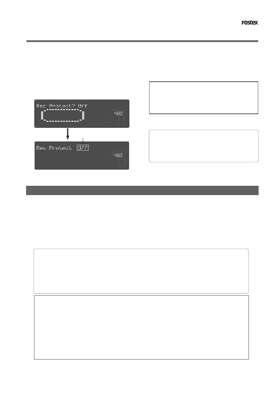
2.Turn the [JOG] dial to select “Rec Protect ?” (“?”
flashes), then press the [EXECUTE/YES] key.
The current setting appears on the display.
Pressing the [
EXECUTE/YES
] key turns off the flashing
“
?
” character, and the recording enabled/disabled
indicator flashes. With the initial setting, “
Off
” flashes
as shown below.
3.Use the [JOG] dial to enable or disable recording.
Rotating the [
JOG
] dial clockwise and counter-clockwise
will flash “
On
” and “
Off
” alternately.
Selecting “
Off
” enables recording; you can record, paste,
and erase data.
Selecting “
On
” disables recording; and you cannot
record, paste, or erase data.
When recording is disabled (On) and you try to record,
paste, or erase data, the recorder displays “Protected”
for a second, indicating that you cannot perform the
operation. To perform the operation, you need to enable
recording (Off).
4.Press the [EXECUTE/YES] key.
To cancel the operation, or to restore the setting
obtained prior to the [EXECUTE/YES] key press, press
the [STOP] button or the [EXIT/NO] key. Each time
you press one of these keys, the recorder returns to
the previous hierarchy level of the menu, and finally
exits SETUP mode and displays the previous Time Base.
Setting digital input (“D. in ?” menu)
In the “Setting a digital input” menu, the signal to be input to the DATA INPUT connector of the recorder can
be set for either digital signals (adat digital signal or S/P DIF digital signal) or analog signals, and also setup of
the digital in clock (synchronous or asynchronous).
By using this function, signals from external digital equipment (CD, MD, DAT, adat digital mixer) can be
digitally recorded.
When selecting the clock, there are the Async and Sync modes; either should be selected depending on the
application. If it is set to “Async mode,” the later explained [Clock Sel?] (Setting the operating clock) should
be setup in accordance to the application.
• Initial setting:
[Analog]
• Assignable digital signal/setting digital in-clock: [adat: Async] (adat digital signal/Asynchronous mode)
[adat: Sync] (adat digital signal/Synchronous mode)
[SPDIF: Async] (S/P DIF digital signal/Asynchronous mode)
[SPDIF: Sync] (S/P DIF digital signal/Synchronous mode)
[Analog] (not assigned digital signal)
* This setting is shared by all Programs in the same disk.
* The settings cannot be saved and loaded as part of the song data.
* The settings are maintained after you turn off the power to the recorder.
If the digital input is set up for Analog (Initial setting), digital signals cannot be input at DATA INPUT 1-8, 9-16
and 17-24 of the D2424.
If the digital input is set up for S/P DIF (Async or Sync), only DATA INPUT 1-8 can be used.
S/P DIF digital signals input to DATA INPUT 1-8 will be assigned and recorded in tracks 1 and 2 of D2424.
If the digital input is set up for adat (Async or Sync), all DATA INPUT connectors can be used.
Adat digital signals input to DATA INPUT 1-8 will be assigned and recorded in tracks 1-8; the signals to INPUT
9-16 in tracks 9-16; and the signals to INPUT 17-24 in tracks 17-24.
∞
42
OL
0
30
24
18
12
9
6
3
kHz
24
FS
BIT
SETUP
24
∞
42
OL
0
30
24
18
12
9
6
3
23
22
21
20
19
18
17
16
15
14
13
12
11
10
9
8
7
6
5
4
3
2
1
CLOCK
INT
∞
42
OL
0
30
24
18
12
9
6
3
kHz
24
FS
BIT
SETUP
24
∞
42
OL
0
30
24
18
12
9
6
3
23
22
21
20
19
18
17
16
15
14
13
12
11
10
9
8
7
6
5
4
3
2
1
CLOCK
INT