1 examining a problem, 1 scanner board diagnostic leds – Epson EM07ZS1647F User Manual
Page 90
4. Troubleshooting (DeviceNet)
4.1.1 Examining a Problem
4.1.1.1 Scanner Board Diagnostic LEDs
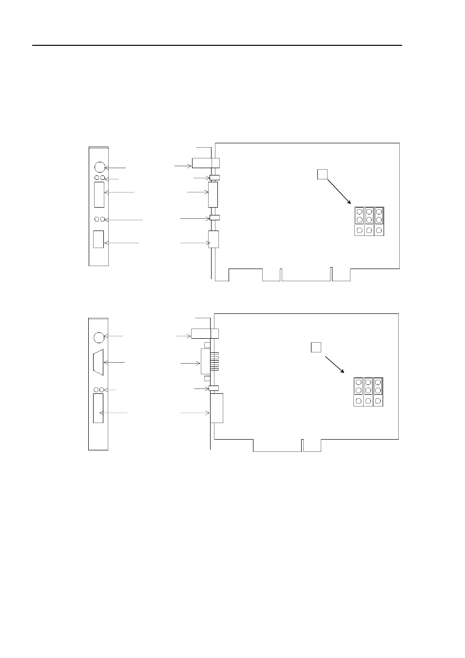
The DeviceNet board used with EPSON RC+ has two status display LEDs. The layout of the
LEDs is shown in the following figure.
PCU-DVNIO
4-pin Terminal
Watchdog Port
(Do not use this port.)
DeviceNet Port
LED (2)
(Not in use)
RJ45 Connector
(Not in use)
C0 C1 C2
JP1
JP1
0
1
Jumper for Board Address
Status Display LED (2)
PCI-DVNIO
Male 9-pin D-Sub
Port for Board Configuration
C0 C1 C2
JP1
JP1
0
1
4-pin Terminal
Watchdog Port
(Do not use this port.)
Status Display LED (2)
Left: Module/NetWork LED
Right: IO LED
DeviceNet Port
Jumper for Board Address
The Module/NetWork LED is on the left and the IO LED is on the right seen from the rear
panel. These LED names are used in applicomIO Console application and this manual. Only
in this troubleshooting section, general names of the status display of the DeviceNet device
are used instead.
The Module/NetWork LED is expressed by the Network Status (NS) in this section.
The IO LED is expressed by the Module Status LED (MS) in this section.
78
Fieldbus I/O Rev.6