8 profibus dp board installation, 1 board appearance – Epson EM07ZS1647F User Manual
Page 53
2. Installation
2.8 PROFIBUS DP Board Installation
Following two board types can be used for the fieldbus I/O option PROFIBUS DP.
- PCU-DPIO
- PCI-DPIO
2.8.1 Board Appearance
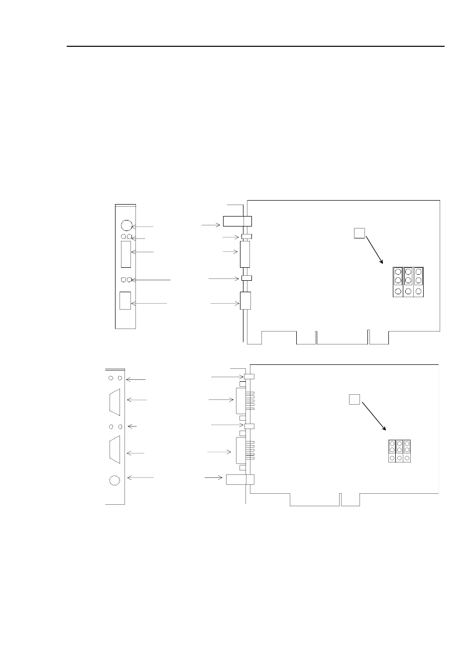
Part names and functions of the scanner board are shown in the following figure. For details
of the status display LEDs, refer to the 4. Troubleshooting in this manual.
PCU-DPIO
C0 C1 C2
JP1
JP1
0
1
PROFIBUS-DP Port
LED (2)
(Not in use)
RJ45 Connector
(Not in use)
4-pin Terminal
Watchdog Port
(Do not use this port.)
Jumper for Board Address
Status Display LED (2)
PCI-DPIO
C0 C1 C2
JP1
JP1
0
1
Configuration Port
Communication Status LED
Male 9-pin D-Sub
Port for Board Configuration
Status Display LED (2)
Left: Communication Status LED
Right: Physical Error LED
Jumper for Board Address
Female 9-pin D-Sub
PROFIBUS DP Port
4-pin Terminal
Watchdog Port
(Do not use this port.)
Fieldbus I/O Rev.6
41
- C8230 (29 pages)
- 400 (38 pages)
- 400 (148 pages)
- 600 (135 pages)
- 640 (45 pages)
- 700 (10 pages)
- 850 (147 pages)
- 1520 (40 pages)
- C82314 (71 pages)
- RS-485 (2 pages)
- 6200A (97 pages)
- C82307 (37 pages)
- UB E02 (86 pages)
- 440 (240 pages)
- 440 (212 pages)
- 660 (92 pages)
- 5000 (176 pages)
- 5000 (154 pages)
- 9000 (68 pages)
- ARM.POWERED ARM720T (224 pages)
- SD-DSPUSBB (2 pages)
- CMD-2260 (18 pages)
- C823301 (17 pages)
- S1C6200A (98 pages)
- 33+ (10 pages)
- FEH300b (46 pages)
- SED 1520 Series (40 pages)
- Serial Interface GQ-3500 (13 pages)
- ETX-945 (39 pages)
- Photo EX (35 pages)
- C82364 (279 pages)
- 214D-1 (57 pages)
- Connect-It SD-DSWIFIB (2 pages)
- ACTIONPC 7000 (10 pages)
- S5U1C63000H2 (35 pages)
- C824 (4 pages)
- C82069* (46 pages)
- 80211b (68 pages)
- C82312 (13 pages)
- S5U1C17801T1100 (60 pages)
- C82324* (57 pages)
- C82372 (22 pages)
- C82315 (48 pages)
- P07303 (36 pages)