1 examining a problem, 1 scanner board diagnostic leds – Epson EM07ZS1647F User Manual
Page 153
4. Troubleshooting (EtherNet/IP)
4.3.1 Examining a Problem
4.3.1.1 Scanner Board Diagnostic LEDs
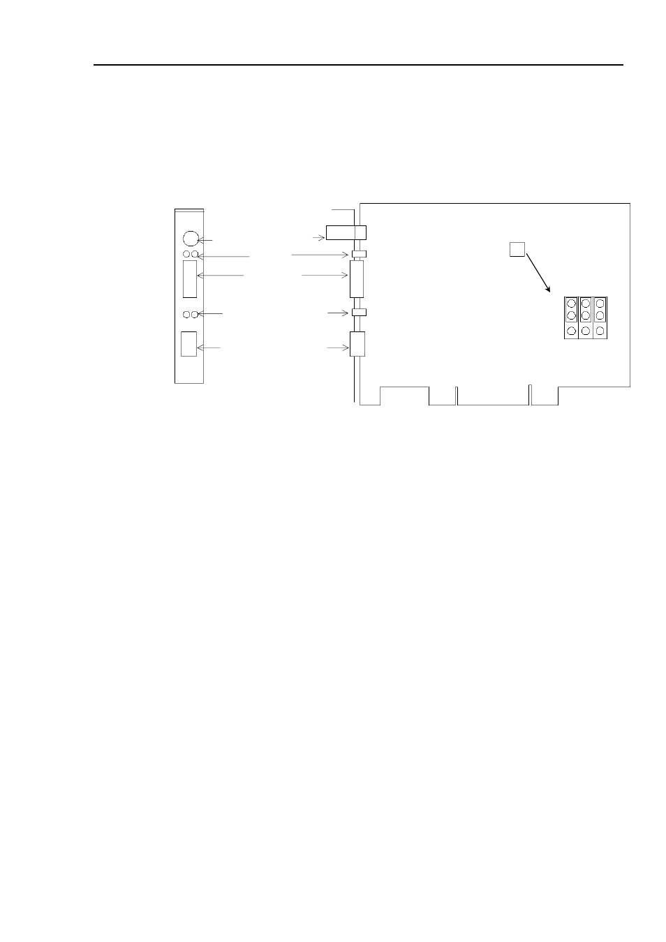
The EtherNet/IP board used with EPSON RC+ has two status display LEDs. The layout of
the LEDs is shown in the following figure.
PCU-ETHIO
C0 C1 C2
JP1
JP1
0
1
D-Sub 9 pin
(Not in use)
Status Display LED (2)
EtherNetI/P Connector
4-pin Terminal
Watchdog Port
(Do not use this port.)
Jumper for Board Address
LED (2)
(Not in use)
The Module/NetWork LED is on the left and the IO LED is on the right seen from the rear
panel. These LED names are used in applicomIO Console application and this manual. Only
in this troubleshooting section, general names of the status display of the DeviceNet device
are used instead.
The Network Status LED is expressed by the NS LED (NS) in this section.
The Module Status LED is expressed by the MS LED (MS) in this section.
Fieldbus I/O Rev.6
141
- C8230 (29 pages)
- 400 (38 pages)
- 400 (148 pages)
- 600 (135 pages)
- 640 (45 pages)
- 700 (10 pages)
- 850 (147 pages)
- 1520 (40 pages)
- C82314 (71 pages)
- RS-485 (2 pages)
- 6200A (97 pages)
- C82307 (37 pages)
- UB E02 (86 pages)
- 440 (240 pages)
- 440 (212 pages)
- 660 (92 pages)
- 5000 (154 pages)
- 5000 (176 pages)
- 9000 (68 pages)
- ARM.POWERED ARM720T (224 pages)
- SD-DSPUSBB (2 pages)
- CMD-2260 (18 pages)
- C823301 (17 pages)
- S1C6200A (98 pages)
- 33+ (10 pages)
- FEH300b (46 pages)
- SED 1520 Series (40 pages)
- Serial Interface GQ-3500 (13 pages)
- ETX-945 (39 pages)
- Photo EX (35 pages)
- C82364 (279 pages)
- 214D-1 (57 pages)
- Connect-It SD-DSWIFIB (2 pages)
- ACTIONPC 7000 (10 pages)
- S5U1C63000H2 (35 pages)
- C824 (4 pages)
- C82069* (46 pages)
- 80211b (68 pages)
- C82312 (13 pages)
- S5U1C17801T1100 (60 pages)
- C82324* (57 pages)
- C82372 (22 pages)
- C82315 (48 pages)
- P07303 (36 pages)