9 fieldbus i/o response performance, Devicenet – Epson EM07ZS1647F User Manual
Page 86
3. Operation
3.9 Fieldbus I/O Response Performance
As mentioned previously, respond times for fieldbus I/O can vary and depend on several
factors. The values in this section are shown for reference not for guaranteed performance.
DeviceNet
Test Environment
RC520 Controller: Pentium III 850 MHz 128 MB memory
Fieldbus I/O:
PCI-DVNIO board Master (MAC ID: 0)
Baud rate:
500 kbps, 125 kbps
Connected Slave: Woodhead 16-input module (TDN-8C0-108)
Node
address:
2
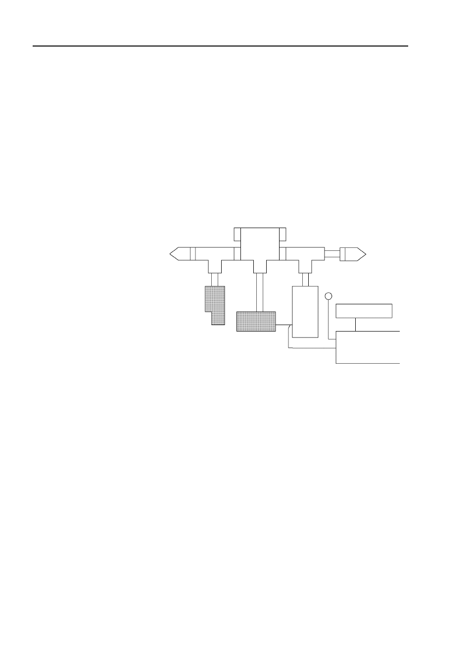
Connection Image
Power Tap
T-branch
Terminating
Resistor
To Standard Input
Waveform
Generator
Power Supply
+24V
NPN Output
PNP Output
Waveform
Modification Jig
In
put Mod
u
le
D
evi
ce
N
et
I/F
B
oard
T-branch
Terminating
Resistor
Evaluation
Signals with various pulse widths (every 5 msec) were input to the standard
I/O input and the input module of the fieldbus I/O at 1 Hz. For 10 minutes
(600 seconds), pulse widths of the received signals were measured at 125
kbps and 500 kbps.
Result
500 kbps: The input devices responded to 25-msec pulse.
125 kbps: The input devices responded to 30-msec pulse.
74
Fieldbus I/O Rev.6