Menu list – Roland VR-6HD Direct Streaming AV Mixer User Manual
Page 140

140
Menu List
Menu item
Value (bold text: default
value)
Explanation
AUDIO EFFECT ASSIGN
Specifies the function that is assigned to the AUDIO EFFECT [1]–[3] button.
AUDIO EFFECT 1–3
CATEGORY
VALUE
Explanation
N/A
––
No function is assigned.
AUDIO INPUT MUTE
(*)
Turns the mute function on/off for the input audio.
AUDIO OUTPUT MUTE
MAIN BUS
AUX 1–2 BUS
USB OUT
STREAM/RECORD
Turns the mute function on/off for the output audio.
AUDIO INPUT SOLO
(*)
Turns the solo function on/off for the input audio.
AUDIO OUTPUT SOLO
MAIN BUS
AUX 1–2 BUS
Turns the solo function on/off for the output audio.
HPF 80Hz
(*)
Turns the high pass filter function on/off.
ECHO CANCELLER
AUDIO IN 1–2
Turns the echo canceller function on/off.
ANTI-FEEDBACK
AUDIO IN 1–2
Turns the anti-feedback function on/off.
NOISE GATE
(*)
Turns the noise gate function on/off.
DE-ESSER
AUDIO IN 1–6
Turns the de-esser function on/off.
COMPRESSOR
(*)
Turns the compressor function on/off.
AUDIO IN EQ
(*)
Turns the equalizer function on/off for the output audio.
AUDIO OUT EQ
MAIN BUS
AUX 1–2 BUS
USB OUT
STREAM/RECORD
Turns the equalizer function on/off for the input audio.
AUDIO OUT GEQ
MAIN BUS
AUX 1–2 BUS
Turns the graphic equalizer function on/off.
VOICE CHANGER
AUDIO IN 1–2
Turns the voice changer function on/off.
AUTO MIXING
––
Turns the auto mixing function on/off.
REVERB(MOMENTARY)
––
Reverb turns on only while you press the button.
REVERB(ALTERNATE)
––
Turns reverb on/off.
AUDIO OUT COMP/LMT
MAIN BUS
AUX 1–2 BUS
Turns the compressor/limiter function on/off.
LOUDNESS AGC
––
Turns loudness auto gain control on/off.
ADAPTIVE NR
––
Turns adaptive noise reduction on/off.
(*) AUDIO IN 1–7/8, USB IN, Bluetooth IN, AUDIO PLAYER, VIDEO 1–6, V.PLAYER
MONITOR SELECT ASSIGN
These settings are for the monitoring video assigned to the MONITOR button.
Menu item
Value
Explanation
MONITOR SELECT
1–4
N/A
No video is assigned.
MULTI-VIEW
The final output video, preview output video and the videos
allocated to the VIDEO SWITCHER [1]–[6] buttons are shown in
sections of the display (multi-view).
STILL-VIEW
Shows the loaded still images in 16 separate sections on the screen.
PROGRAM
Shows the final output video.
SUB PROGRAM
Shows the SUB PROGRAM bus video.
PREVIEW
Shows the preview output video.
AUX
Shows the AUX bus video.
AUDIO LEVEL
Shows the audio level screen.
DASHBOARD
ENTER
Shows the dashboard screen.
MULTI-VIEW SETTINGS
ENTER
Configures the multi-view.
TALLY FRAME
Sets whether to display the tally frame or not in the monitor.
MULTI-VIEW
OFF,
ON
Turns the tally frame on/off in the MULTI-VIEW.
STILL-VIEW
OFF,
ON
Turns the tally frame on/off in the STILL-VIEW.
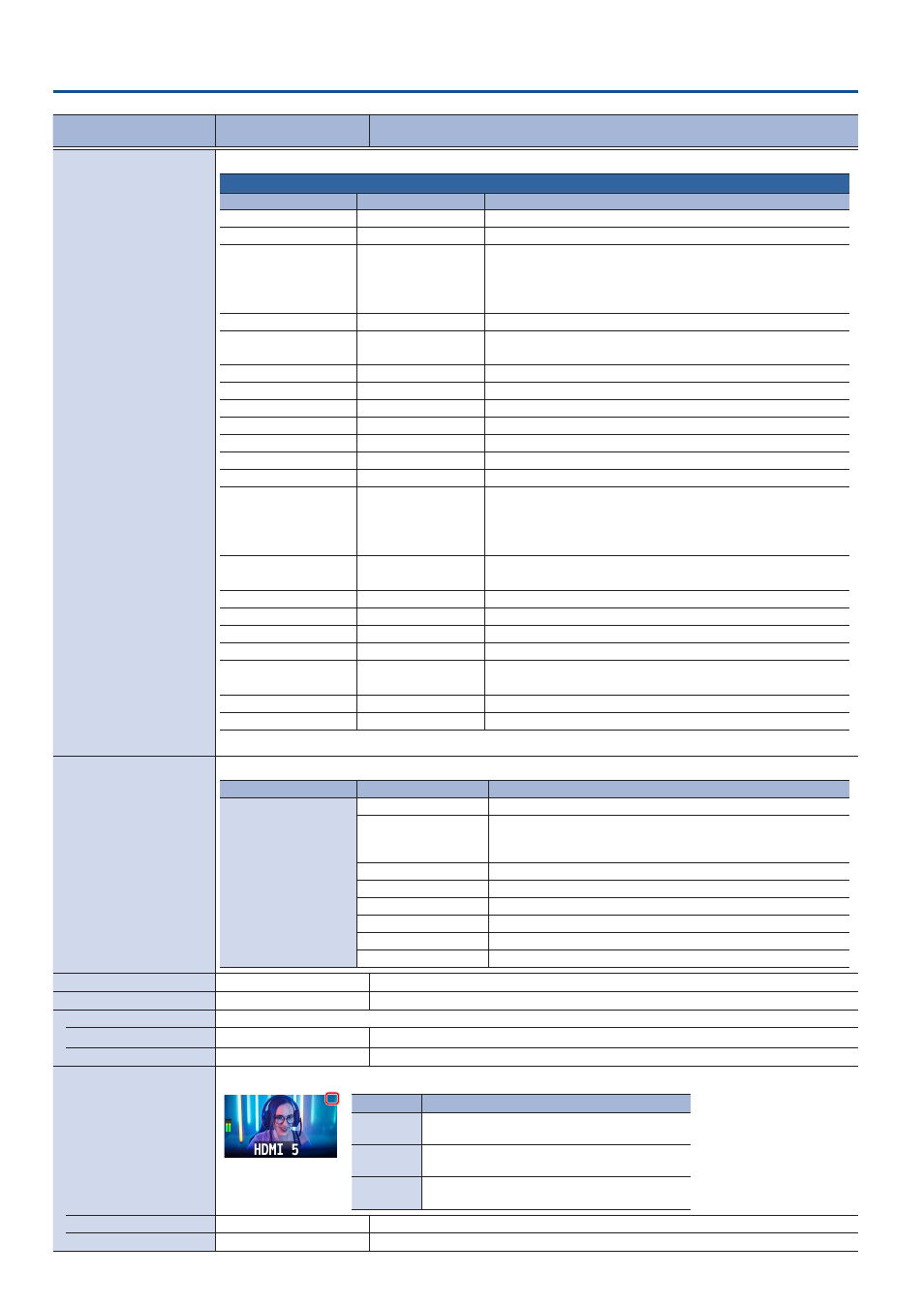
AUX/SOURCE INDICATOR
Sets whether to display the AUX indicator in the monitor.
Color
Explanation
Yellow
Shows that this has been selected as an inset
screen for the PinP & KEY.
Magenta
Shows that this has been selected as a DSK video
source.
Green
Shows that this has been selected as an AUX bus
video source.
MULTI-VIEW
OFF,
ON
Turns the AUX indicator on/off for multi-view.
STILL-VIEW
OFF,
ON
Turns the AUX indicator on/off for still-view.
