4 dc connection, 1 requirements for the dc connection, Dc connection – SMA SB 3600SE-10 User Manual
Page 34: Requirements for the dc connection
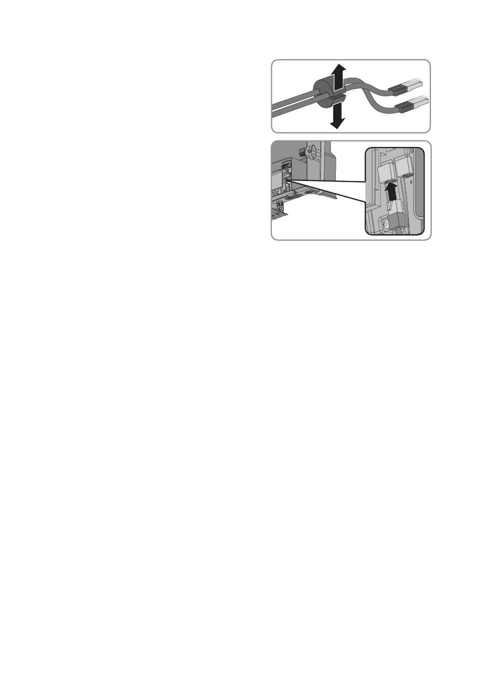
9. Route each network cable through a separate
opening in the cable support sleeve.
10. Lead the network cables through the cable
gland M32x1.5 to the network ports in the
inverter. Press the cable support sleeve firmly into
the cable gland.
11. Insert the network cables into the network ports A and B in the inverter. The assignment of the
network cables to the pin connectors is not relevant, as the pin connectors constitute a switch
function.
12. Connect the ends of the network cables to the SMA Energy Meter and the router/network
switch.
13. Screw the swivel nut onto the cable gland.
14. Flip the display down until it snaps into place.
6.4 DC Connection
6.4.1
Requirements for the DC Connection
Requirements for the PV modules per input:
☐ All PV modules must be of the same type.
☐ The same number of series-connected PV modules must be connected to each string.
☐ All PV modules must be aligned identically.
☐ All PV modules must have the same tilt angle.
☐ The maximum input current per string must be maintained and must not exceed the through-
fault current of the DC connectors (see Section 11 "Technical Data", page 57).
☐ The thresholds for the input voltage and the input current of the inverter must be adhered to
(see Section 11 "Technical Data", page 57).
☐ On the coldest day based on statistical records, the open-circuit voltage of the PV array must
never exceed the maximum input voltage of the inverter.
☐ The positive connection cables of the PV modules must be fitted with the positive DC
connectors (for information on assembling DC connectors, see the DC connector installation
manual).
☐ The negative connection cables of the PV modules must be fitted with the negative DC
connectors (for information on assembling DC connectors, see the DC connector installation
manual).
6 Electrical Connection
SMA Solar Technology AG
Operating Manual
SB36-50SE-BE-en-11
34