6 electrical connection, 1 overview of the connection areas, 1 view from below – SMA SB 3600SE-10 User Manual
Page 27: Electrical connection, Overview of the connection areas, View from below
6 Electrical Connection
6.1 Overview of the Connection Areas
6.1.1
View from Below
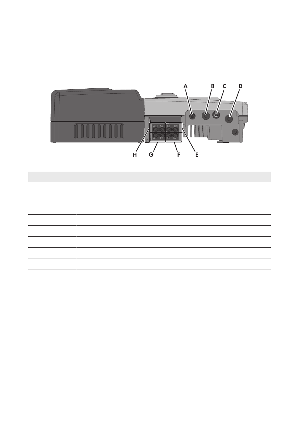
Figure 8: Connection areas and enclosure openings at the bottom of the inverter
Position
Designation
A
Cable gland M20x1.5 for the connection to the multifunction relay
B
Enclosure opening with filler plug for the data cable
C
USB pin connector for service purposes (e.g., firmware update)
D
Enclosure opening for the AC cable
E
Positive DC connectors, input B
F
Negative DC connectors, input B
G
Negative DC connectors, input A
H
Positive DC connectors, input A
6 Electrical Connection
SMA Solar Technology AG
Operating Manual
27
SB36-50SE-BE-en-11
This manual is related to the following products: