HEIDENHAIN IK 5294 User Manual
Page 106
86
QC5200 Series User’s Guide
The level plane feature will be added
to the Features template.
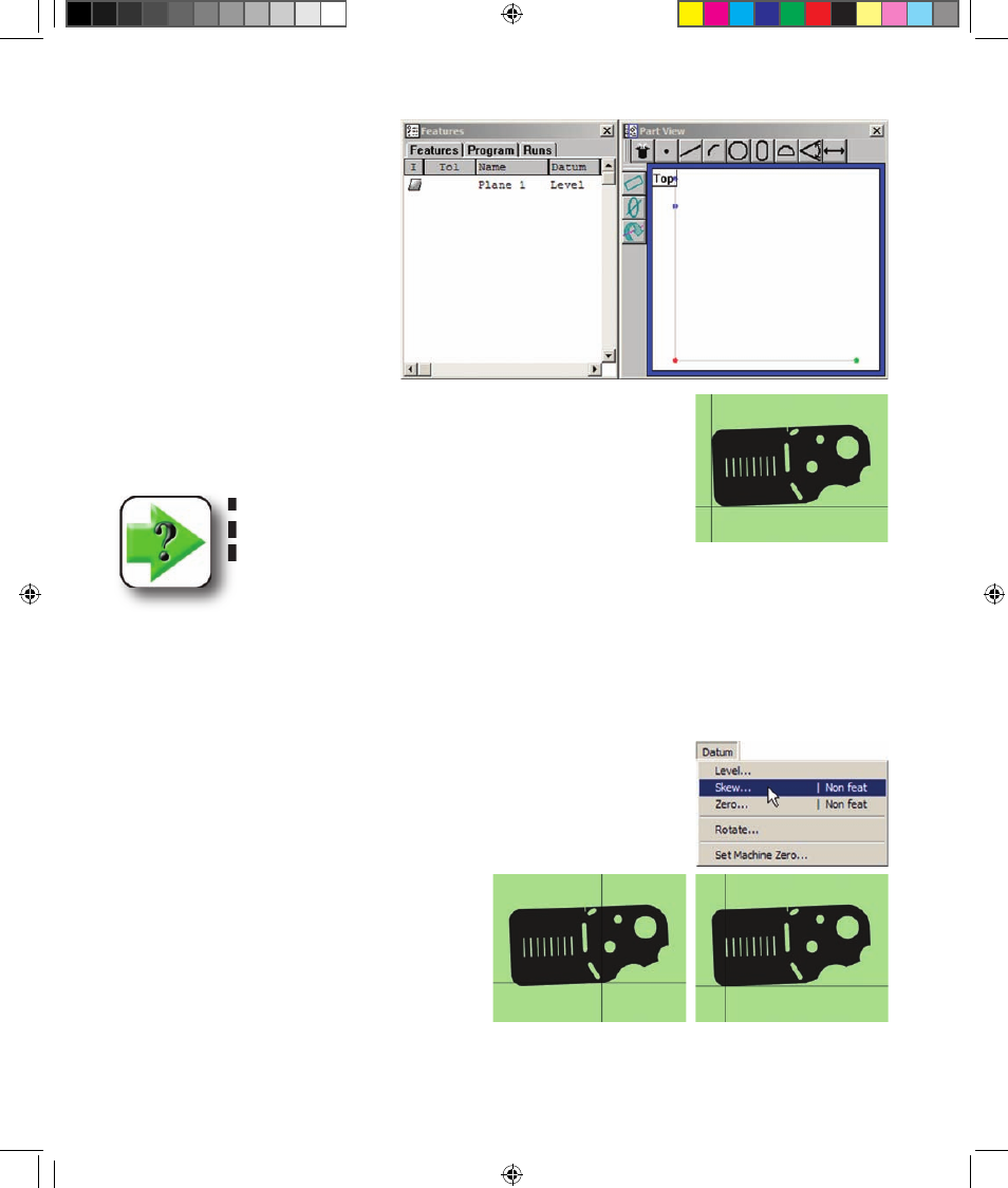
Creating the skew alignment
When the part is misaligned (twisted) in the X-Y plane, small cosine errors
can be generated during the measurement process.
NOTE
The X-Y misalignment shown here is exaggerated for em-
phasis.
These errors can be eliminated by creating a skew alignment for the part. The skew alignment includes a
precise measurement of the part misalignment. Once the misalignment is known to the system, subsequent
feature measurements are automatically compensated to eliminate cosine errors. Measurement data in
the Results window and feature images in the Part View window will reflect measurements of a perfectly
aligned part.
To create a skew alignment:
1 Click the Datum/Skew menu item. A description of the skew alignment
process will be displayed in a prompt window.
2 Perform a skew alignment by probing 2 or
more points well distributed along the entire
length of the desired part reference edge, and then
click OK in the prompt window.
The bottom edge of the part is probed to perform skew
alignment on the x-axis
5 Measuring OE.indd 4
5/9/2005 9:59:42 AM