HEIDENHAIN CNC Pilot 4290 Pilot User Manual
Page 33
33
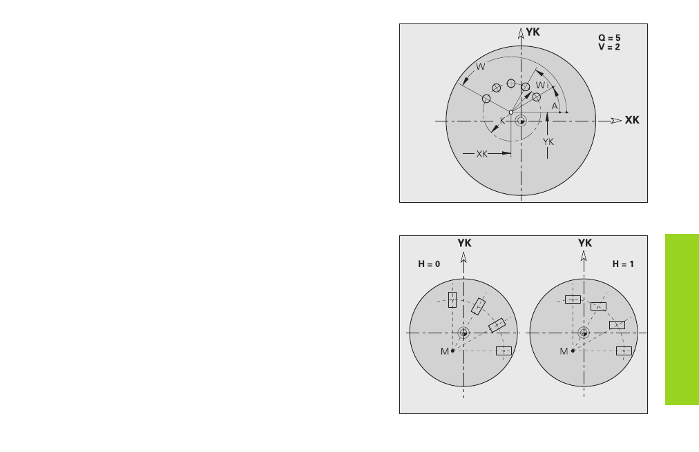
Circular pattern on end face G402-Geo
G402 defines a circular pattern on the front/rear end face. G402 is
effective for the figure defined in the following block (G300..305, G307).
Programming notes
■
Program the hole/figure in the following block without a center –
exception: circular slot.
■
The milling cycle (MACHINING section) calls the hole/figure in the
following block - not the pattern definition.
Parameters
Q:
Number of figures
K:
Pattern diameter
A, W: Starting angle, end angle – position of first/last figure (reference:
XK-axis) – default: A=0°; W=360°
Wi:
Angle between two figures
V:
Direction (orientation) – default: 0
■
V=0 – without W: Distribution over complete circle
■
V=0 – with W: Distribution over long arc
■
V=0 – with Wi: Algebraic sign of Wi defines the direction
(Wi<0: Pattern in clockwise direction)
■
V=1 – with W: Pattern in clockwise direction
■
V=1 – with Wi: Pattern in clockwise direction (algebraic sign of
Wi is without meaning)
■
V=2 – with W: Pattern counterclockwise
■
V=2 – with Wi: Pattern counterclockwise (algebraic sign of Wi
has no effect)
XK,YK: Center of pattern
H:
Position of figures – default: 0
■
H=0: Normal position – figures are rotated about the circle
center (rotation)
■
H=1: Original position – position of figure remains the
unchanged with respect to the coordinate system (translation)
Figur
es on end f
ace cont
our