HEIDENHAIN CNC Pilot 4290 Pilot User Manual
Page 20
20
Thread (general) G37-Geo
G37 defines the different types of thread. Threads are interlinked by
programming several G01/G34 blocks after each other.
Parameters
Q:
Type of thread – default: 1
■
Q=1: metric ISO fine-pitch thread (DIN 13 Part 2, Series 1)
■
Q=2: metric ISO thread (DIN 13 Part 1, Series 1)
■
Q=3: metric ISO taper thread (DIN 158)
■
Q=4: metric ISO tapered fine-pitch (DIN 158)
■
Q=5: metric ISO trapezoid thread (DIN 103 Part 2, Series 1)
■
Q=6: flat metric trapezoid thread (DIN 308 Part 2, Series 1)
■
Q=7: metric buttress thread (DIN 13 Part 2, Series 1)
■
Q=8: cylindrical round thread (DIN 405 Part 1, Series 1)
■
Q=9: cylindrical Whitworth thread (DIN 259)
■
Q=10: tapered Whitworth thread (DIN 2999)
■
Q=11: Whitworth pipe thread (DIN 2999)
■
Q=12: nonstandard thread
■
Q=13: UNC US coarse thread
■
Q=14: UNF US fine-pitch thread
■
Q=15: UNEF US extra-fine-pitch thread
■
Q=16: NPT US taper pipe thread
■
Q=17: NPTF US taper dryseal pipe thread
■
Q=18: NPSC US cylindrical pipe thread with lubricant
■
Q=19: NPFS US cylindrical pipe thread without lubricant
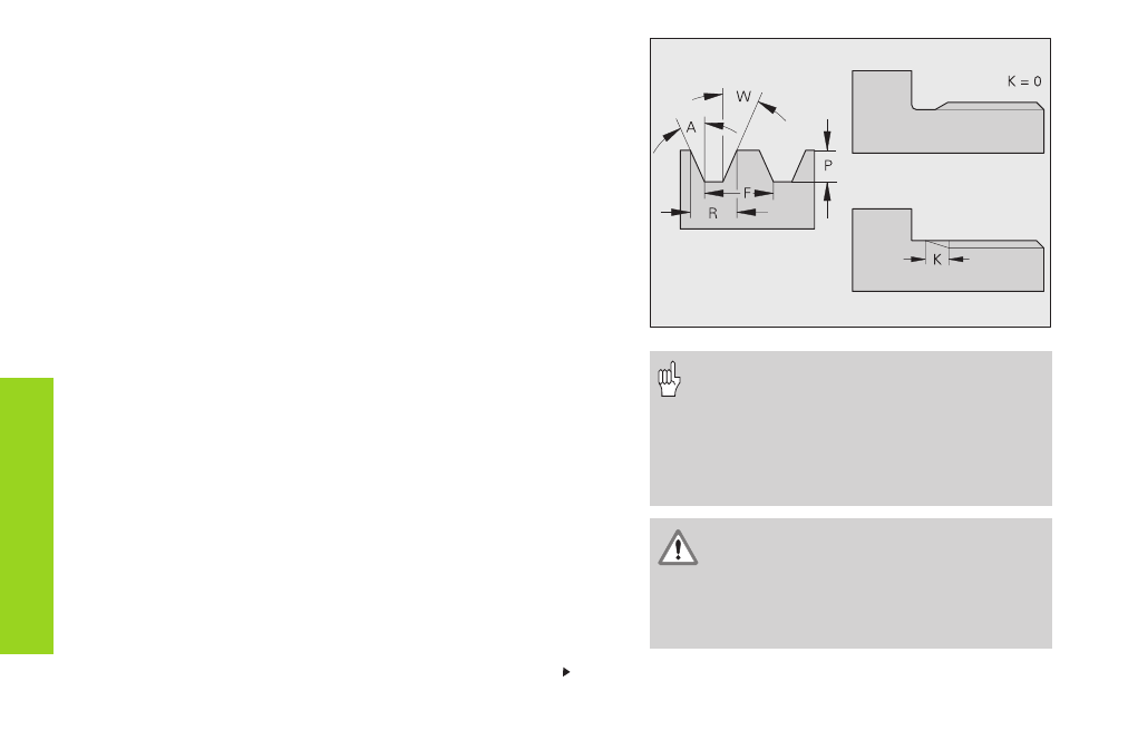
F:
Thread pitch – must be entered for Q=1, 3..7, 12.
P:
Thread depth – enter only for Q=12.
K:
Runout length (for threads without undercut) –
default: 0
F
o
rm
elements
fo
r cont
our descr
iption
• Program a linear contour element as a
reference before G37.
• The thread is cut with G31.
• For standard threads, the parameters P, R,
A and W are defined by the CNC PILOT.
• Use Q=12 if you wish to use individual
parameters.
The thread is generated to the length of the
reference element. For the machining of
threads without an undercut, it is necessary
to program an additional linear element so
that the overrun can be executed by the CNC
PILOT without danger of collision.
Continued