Ii - 5 measured value output, Starting measured value output – HEIDENHAIN PT 855 for Turning User Manual
Page 75
II - 5
Measured Value Output
POSITIP 855
Technical Information
77
II - 5
Measured Value Output
POSITIP can output measured values over the data interface.
Starting measured value output
There are two ways to start measured value output:
•
Transmit control character to the data interface
•
Send signal to switching input
The delay between the latch signal and measured value output de-
pends on the selected signal.
Transit time of encoder signals
After approximately 4 µs the encoder signals are present in a
buffer that is interrogated by the internal latch signal. The meas-
ured value that is output is therefore the value that existed approxi-
mately 4 µs prior to the internal latch.
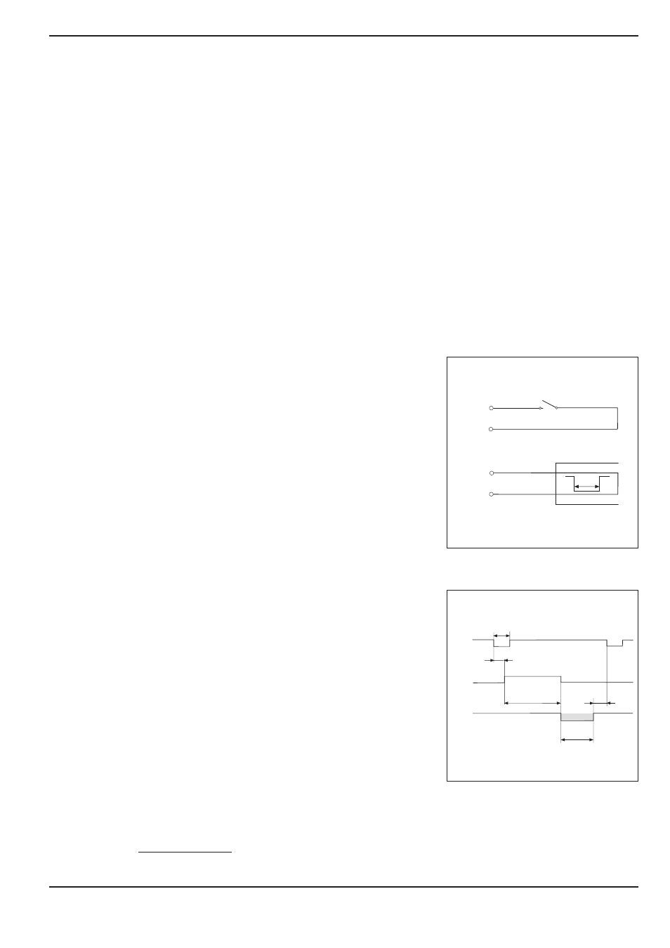
Starting measured value output over external switching input
You can start measured value output over the switching input at
the D-sub connection EXT by sending a pulse or by make contact.
Contact at pin 9: make contact against 0 V
Pulse at pin 8: pulse duration t
e
≥
1.2 µs
The contact or pulse can also be sent over a TTL logic device
(such as SN 74 LS XX):
U
H
≥
3.9 V (U
MAX
= 15 V)
U
L
≤
0.9 V with I
L
≤
6 mA
E X T
P I N 9
P I N 1
( 0 V )
P I N 8
P I N 1
( 0 V )
t
e
E X T
t
1
t
3
t
2
t
D
t
e
T X D
t
e
: Minimum duration, pulse
t
e
≥
1.2 ms
t
e
: Minimum duration, contact
t
e
≥
7 ms
t
1
: Delay between pulse and internal latch
t
1
≤
0.8 µs
t
1
: Delay between contact and internal latch
t
1
≤
4.5 ms
t
2
: Delay between internal latch and measured value output
t
2
≤
30 ms
t
3
: Delay between end of data output and next latch over
external switching input
t
3
≥
0 ms
t
D
: Duration of measured value output
The duration of measured value output (t
D
) depends on:
•
The selected baud rate (BR)
•
The number of axes (M)
•
The number of blank lines (L)
t
D
=
[s]
BR
187
×
M + L
×
11
Fig. 43: Time diagram for measured value out-
put over external switching input
Fig. 42: Signal by make contact against 0 V