Ii - 4 data interface, Data interface, Ii - 4 – HEIDENHAIN PT 855 for Turning User Manual
Page 73
II - 4
Data Interface
POSITIP 855
Technical Information
75
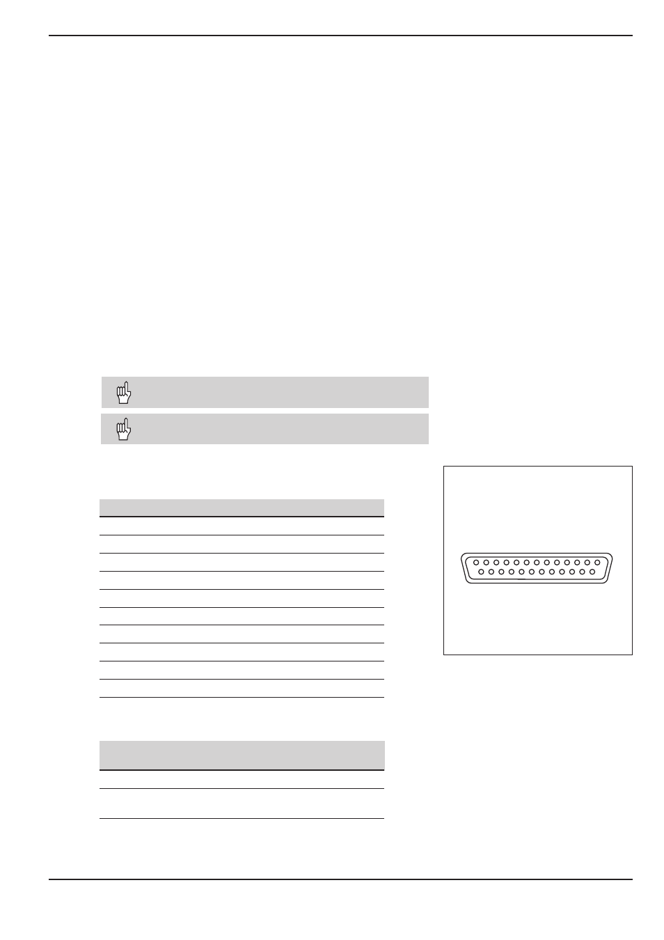
X 3 1 ( R S - 2 3 2 - C / V . 2 4 )
13
10
7
4
1
14
18
21
25
Data Interface
The POSITIP's data interface allows you to save programs and
operating parameters on diskette, or print out or save coordinates.
Chapter I - 3 describes how to transfer programs, and Chapter
II - 2 describes how to transfer operating parameters.
This chapter covers what you need to know about setting up the
data interface:
•
Pin layout of the data interface
•
Signal levels
•
Wiring of the connecting cable and connectors
•
Baud rate (data transfer speed)
•
Data format
Connections
The RS-232-C/V.24 serial port is located on the POSITIP's rear
panel. The following devices can be connected to this port:
•
HEIDENHAIN FE 401 floppy disk unit
•
Printer with serial data interface
•
Personal computer with serial data interface
The HEIDENHAIN FE 401 floppy disk unit is immedi-
ately ready for operation at the data interface.
Interface X31 complies with the recommendations in
VDE 0160, 5.88 for separation from line power.
Pin layout on the POSITIP data interface
Pin
Assignment
1
CHASSIS GND – Chassis ground
2
TXD
– Transmitted data
3
RXD
– Received data
4
RTS
– Request to send
5
CTS
– Clear to send
6
DSR
– Data set ready
7
SIGNAL GND
– Signal ground
20
DTR
– Data terminal ready
8 to 19
Do not assign
21 to 25
Do not assign
Signal levels
Signal
Signal level
Signal level
1 = active
0 = not active
TXD, RXD
– 3 V to – 15 V
+ 3 V to + 15 V
RTS, CTS
+ 3 V to + 15 V
– 3 V to – 15 V
DSR, DTR
II - 4
Fig. 38: Pin layout of RS-232-C/V.24 data
interface