Enterasys Networks Enterasys Matrix 6H303-48 User Manual
Page 85
Memory Locations and Replacement Procedures
Matrix DFE-Gold Series Installation Guide B-5
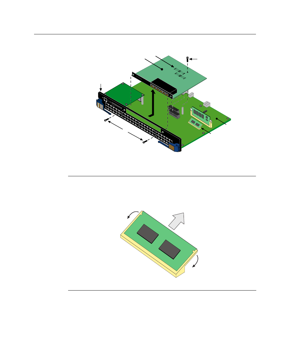
Figure B-4 NEM Removal and DRAM SIMM Connector Location on 4G4282-49
2.
Refer to
. Push the connector arms away from the DRAM SIMM and
simultaneously lift the DRAM SIMM enough to release it from the connector fingers.
Figure B-5 Removing the Existing DRAM SIMM from 4G4282-49
3.
Rotate the DRAM SIMM upward, then remove it from the connector fingers.
1 Network Expansion Module (not on all DFEs)
4 DFE module front panel
2 Main PC board
5 Module connectors on main board
3 Screws (3)
6 DRAM SIMM memory module
1 Connector arms
2 DRAM SIMM
3 Connector fingers
COM
OFFLINE/ RESET
MGMT
CPU
1
2
3
GR
OUP
SELECT
1X
11X
13X
4
12X
14X
23X
24X
25X
26X
35X
36X
37X
38X
47X
48X
G R
O U
P
1
G R
O U
P
2
G R
O U
P
3
G R
O U
P
4
GR
OUP
1
2
3
4
5
6
7
8
9
10
11
12
4G
42
82
-4
9
Gb ENET
DFE
Â
1
2
3
4
5
6
1
2
3
4
5
6
7G-6MGBIC-A
А
Г
В
Б
Д
Е
А
А
Б
В