Nlec by measuring points on a calibration grid, 2 s o ft wa re s e tu p – HEIDENHAIN ND 100 User Manual User Manual
Page 90
90
2 Installation and Specifications
2
.2
S
o
ft
wa
re
s
e
tu
p
NLEC by measuring points on a calibration grid
Position the standard artifact along the measurement axis.
Align the artifact as closely as possible to the axis and then perform
a skew alignment as described in chapter 1 (see "Align the part to a
measurement axis" on page 32).
Create a reference datum by probing the point at the 1,1 position of
the calibration grid and pressing the X and Y Axis keys to zero the
point.
While the crosshair probe is positioned over the 1,1 grid point
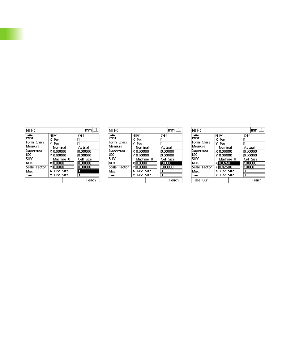
(datum), highlight the NLEC setup menu item.Highlight the X and Y
Grid Size data fields and enter the number of calibration points in the
X and Y axes. In the example, 3 points were entered in the X and Y
Grid Size fields to describe the 3 X 3 calibration grid.
Highlight the X and Y Cell Size data fields and enter the distance
between calibration points on the X and Y axes. In the example, the
distance between points is 1 inch (25.4cm) on the X and Y
axes.Highlight the Machine 0 X or Y data field and press the Use Cur
soft key to enter the offset from the DRO machine zero and the
calibration grid datum. The offsets for both axes will be entered and
displayed automatically by the DRO.
Highlight the X Pos data field. Initially the X Pos and Y Pos fields will
contain values of 1. These values are incremented by the DRO as
the calibration is performed. Press the Teach soft key to begin the
NLEC calibration, then follow the instructions provided on the
screen for conducting measurements. Grid measurement locations
are indicated in the top left corner of the DRO screen during
measurements. Upon completion of the grid measurements the
nominal (certified) and actual (measured) values will be displayed in
the Nominal and Actual data fields for each grid position.
Enter the X and Y calibration grid size
Enter the X and Y cell size
Enter the machine zero offset