2 s o ft wa re s e tu p – HEIDENHAIN ND 100 User Manual User Manual
Page 89
ND 120 QUADRA-CHEK
89
2
.2
S
o
ft
wa
re
s
e
tu
p
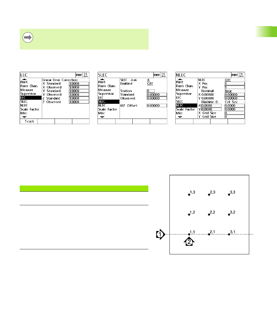
Highlight the SLEC setup menu item and verify that the Enabled
choice field specifies Off.
NLEC correction can not be configured while NLEC is enabled.
Highlight the NLEC setup menu item and verify that the NLEC
choice field specifies Off.
Once these initial steps have been completed, NLEC error correction
can be performed using one of two methods:
By measuring points on a calibration grid
By importing NLEC data from a computer using the USB-to-Serial
connection
In the example of applying NLEC, nine points are measured using a
3 X 3 calibration grid.
Notice
NLEC can not be performed if a different error correction
is already enabled.
Verify that values in the LEC screen are
all 1.000
Verify that SLEC Enable is Off
Verify that the NLEC is Off
Nine points of a 3 X 3 calibration grid are shown with
numeric X,Y grid locations
Arrow number
Descriptions
1: Grid alignment
A Skew alignment is performed to align the
grid perfectly to the X axis.
2: Datum and grid
data points
A zero datum is created at the lower left
corner of the grid. This is the first position
(X=1,Y=1) that will be entered into the
NLEC setup screen.
Other calibration data points to be entered
into the NLEC setup screen are also shown
in the X,Y format (1,1 through 3,3 in this
example).