Introduction – Grass Valley NV9601 v.2.0 User Manual
Page 15
NV9601 Control Panel • User’s Guide
5
1. Introduction
About Levels, Level Sets and Level Mapping
Inter-level set mapping is used when more than one level set is defined and devices in different
level sets need to be connected. Inter-level mapping works by telling the control system exactly
how to connect different level sets.
For information on mapping level sets through the control panel, see
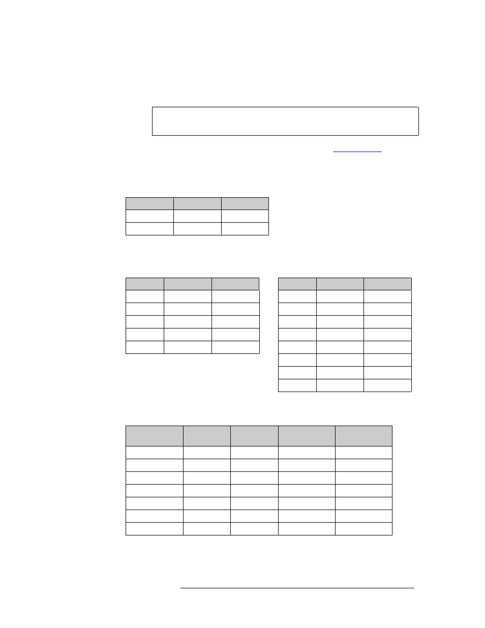
Example:
A system has two router crosspoint matrices, SDI and AES, with physical levels defined as fol-
lows:
In this system are 3 slow-motion cameras and 3 slow-motion VTRs. Each device has 3 SDI sig-
nals, phases 1–3, on 3 connectors. Two level sets are defined, one for High Definition video
(HD) and one for slow-motion (SLOMO):
To route signals from one level set to the other, an inter-level set mapping can be defined as fol-
lows:
The mapping shows that virtual level SDI can be connected to phase 1, 2, or 3 of the VTRs. It
also shows that the 4 AES levels map identically across the two level sets.
Note
All virtual levels in the affected level sets must be in the same physical router
(i.e., all signals must be on the same crosspoint module) or tielines are needed.
Level
Inputs
Outputs
1 SDI
1–288
1–576
2 AES
1–512
1–512
Level Set
Virtual Level
Phys Level
Level Set
Virtual Level
Phys Level
HD
SDI
SDI
SLOMO SDI
SDI
AES 1/2
AES
Phase1
SDI
AES 3/4
AES
Phase2
SDI
AES 5/6
AES
Phase3
SDI
AES 7/8
AES
AES 1/2
AES
AES 3/4
AES
AES 5/6
AES
AES 7/8
AES
Inter-Level Set
Mapping
Upstream
Level Set
Downstream
Level Set
Upstream
Virtual Levels
Downstream
Virtual Levels
HD2SLOMO HD
SLOMO
SDI
Phase1
SDI
Phase2
SDI
Phase3
AES 1/2
AES 1/2
AES 3/4
AES 3/4
AES 5/6
AES 5/6
AES 7/8
AES 7/8