Copperhead 3050 base station, Copperhead 3050 base station front panel, Area a - front panel optical connector (optional) – Grass Valley 3050 CopperHead User Manual
Page 27
21
CopperHead 3050
User Guide
CopperHead 3050 Base Station
The CopperHead 3050 Base Station is available with a number of options. The unit is
ordered with a specified Power Module, Audio/Intercom Module and Fiber Connector. For
an overall view of component location please see the overall diagrams in
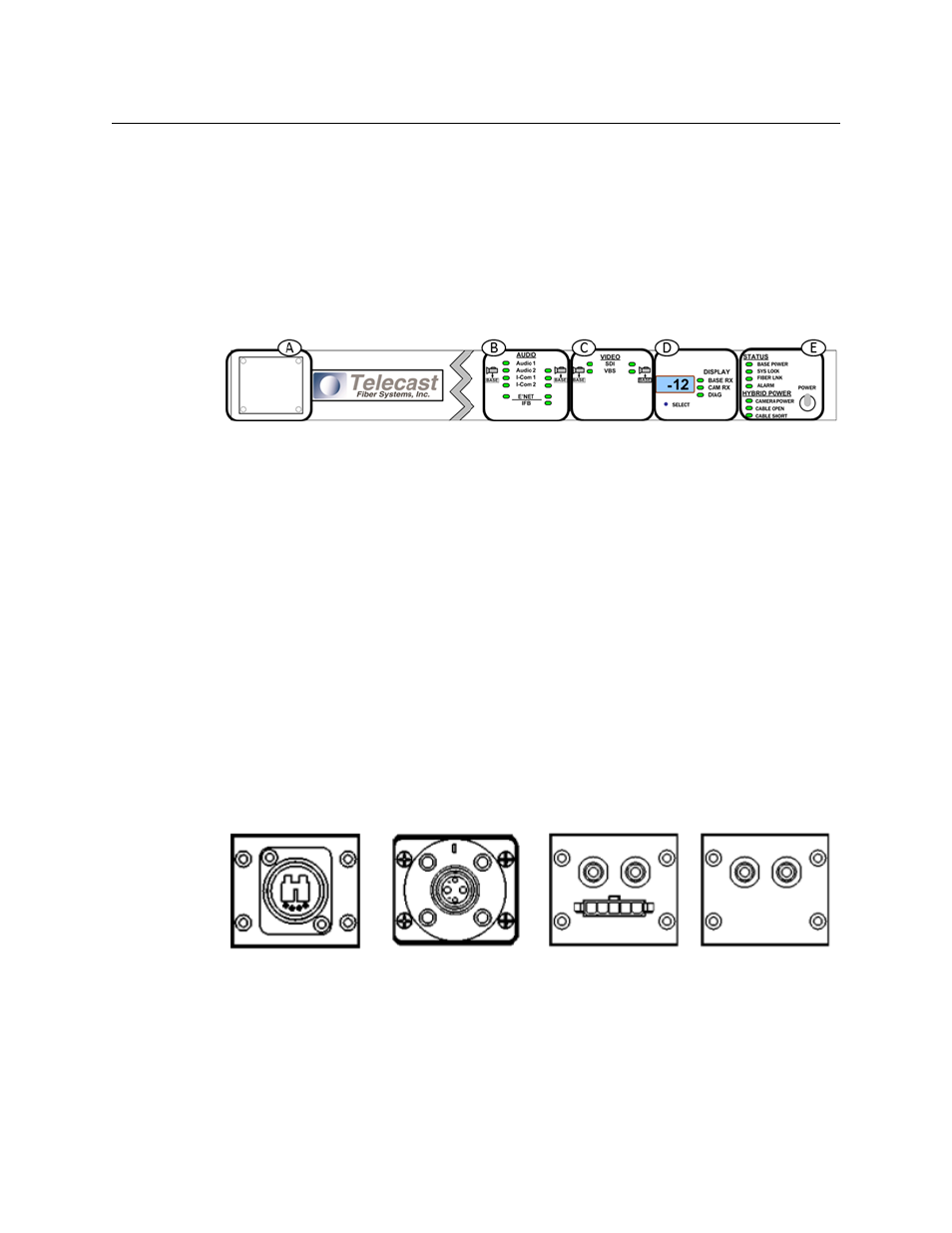
CopperHead 3050 Base Station Front Panel
Fig. 3-11: CopperHead 3050 Base Station Front Panel
• A - Optical Connector (see
Area A - Front Panel Optical Connector (Optional)
• B - Audio/Ethernet Indicators (see
Area C - Video/Data Indicators
• D - Signal Strength Indicators/Setup (see
Area D - Signal Strength Indicators/Setup
• E - Status/Power Indicators (see
Area E - Status/Power Indicators
Area A - Front Panel Optical Connector (Optional)
Area A of the CopperHead 3050 Base Station provides for the optional mounting of the
Fiber Optical Connector on the front of the Base Station instead of the rear of the Base
Station.
For information on how to convert the Base Station from Rear to Front Fiber Connector, see
Connections between the Base Station and the Camera Unit
Three types of Fiber Connectors are available for use with the CopperHead 3050 Base
Station. Typically one of these Fiber Connectors is pre-configured at the time of delivery.
Fig. 3-12: Fiber Connector Types
OpticalCON
SMPTE 304M
Molex and STs
ST Connectors