Fspf configuration example, Network requirements, Configuration procedure – H3C Technologies H3C S10500 Series Switches User Manual
Page 79
68
0x030000/8 STATIC 10 0 Vfc2
0xfffc02/24 DIRECT 0 0 InLoop0
0xfffffa/24 DIRECT 0 0 InLoop0
0xfffffc/24 DIRECT 0 0 InLoop0
0xfffffd/24 DIRECT 0 0 InLoop0
# Display the FC routing table in VSAN 1 on Switch C.
[SwitchC-vsan1] display fc routing-table vsan 1
Routing Table: VSAN 1
Destinations : 6 Routes : 6
Destination/mask Protocol Preference Cost Interface
0x010000/8 STATIC 10 0 Vfc2
0x020000/8 STATIC 10 0 Vfc2
0xfffc03/24 DIRECT 0 0 InLoop0
0xfffffa/24 DIRECT 0 0 InLoop0
0xfffffc/24 DIRECT 0 0 InLoop0
0xfffffd/24 DIRECT 0 0 InLoop0
# FCping Switch C from Switch A.
[SwitchA-vsan1] fcping fcid fffc03 vsan 1
FCPING fcid 0xfffc03: 128 data bytes, press CTRL_C to break
Reply from 0xfffc03: bytes = 128 time = 23 ms
Reply from 0xfffc03: bytes = 128 time = 9 ms
Reply from 0xfffc03: bytes = 128 time = 19 ms
Reply from 0xfffc03: bytes = 128 time = 14 ms
Reply from 0xfffc03: bytes = 128 time = 25 ms
--- 0xfffc03 fcping statistics ---
5 packet(s) transmitted
5 packet(s) received
0.00% packet loss
round-trip min/avg/max = 9/18/25 ms
The output shows that Switch A can reach Switch C.
FSPF configuration example
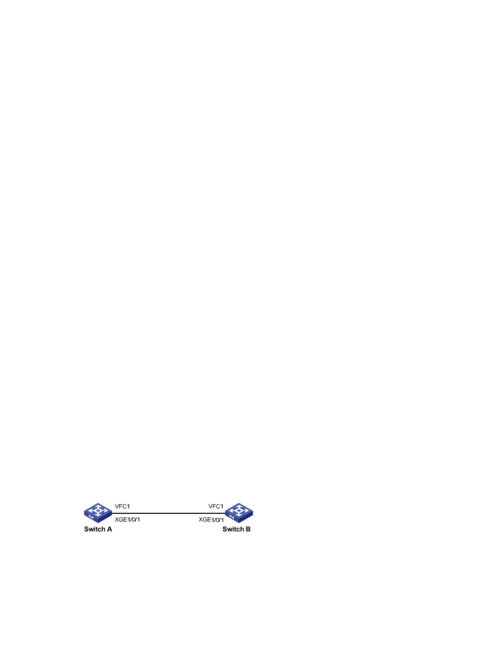
Network requirements
Configure FSPF so the two FCF switches can communicate with each other.
Figure 22 Network diagram
Configuration procedure
This section describes only the FC routing configurations.
1.
Configure Switch A: