Npv mode – H3C Technologies H3C S10500 Series Switches User Manual
Page 21
10
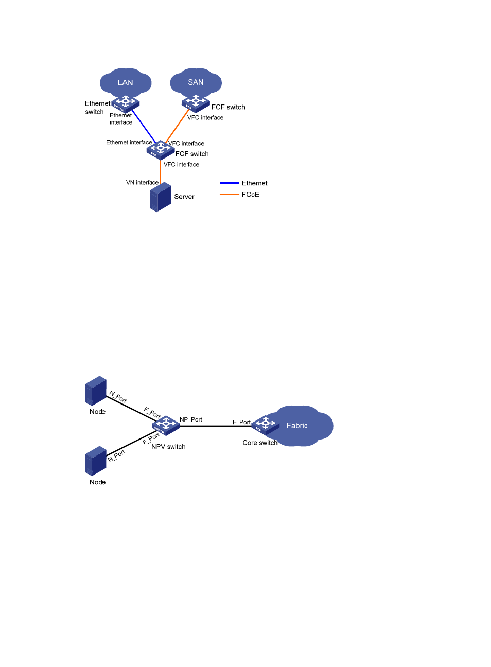
Figure 10 FCF network diagram
In an FCoE environment as shown in
, FCF switches communicate with the ENode over a
lossless Ethernet network. The end of an FCoE virtual link on an FCF switch is a VFC interface. The peer
end of an FCoE virtual link can be a VN interface on an ENode or a VFC interface on another FCF
switch.
Like an FC switch, each FCF switch is assigned a domain ID. Each FC SAN supports a maximum of 239
domain IDs, so an FC SAN cannot have more than 239 switches.
NPV mode
An FC SAN needs a large number of edge switches that are connected directly to nodes. NPV switches
are developed to expand the number of switches in an FC SAN.
Figure 11 NPV network diagram
As shown in
, the NPV switch resides between nodes and the core switch on the edge of the
fabric. The core switch is a switch operating in FCF mode. The NPV switch is connected to the nodes
through its F_Ports and to the core switch through its NP_Port. The NPV switch forwards traffic from its
connected nodes to the core switch.
The NPV switch appears as an FCF switch to nodes and as a node to the core switch.
For more information about NPV, see "