Configuring npv, Overview, Downlink interface and downlink – H3C Technologies H3C S10500 Series Switches User Manual
Page 106: Uplink interface and uplink
95
Configuring NPV
Overview
NPV enables an FC SAN to accommodate more than 239 switches.
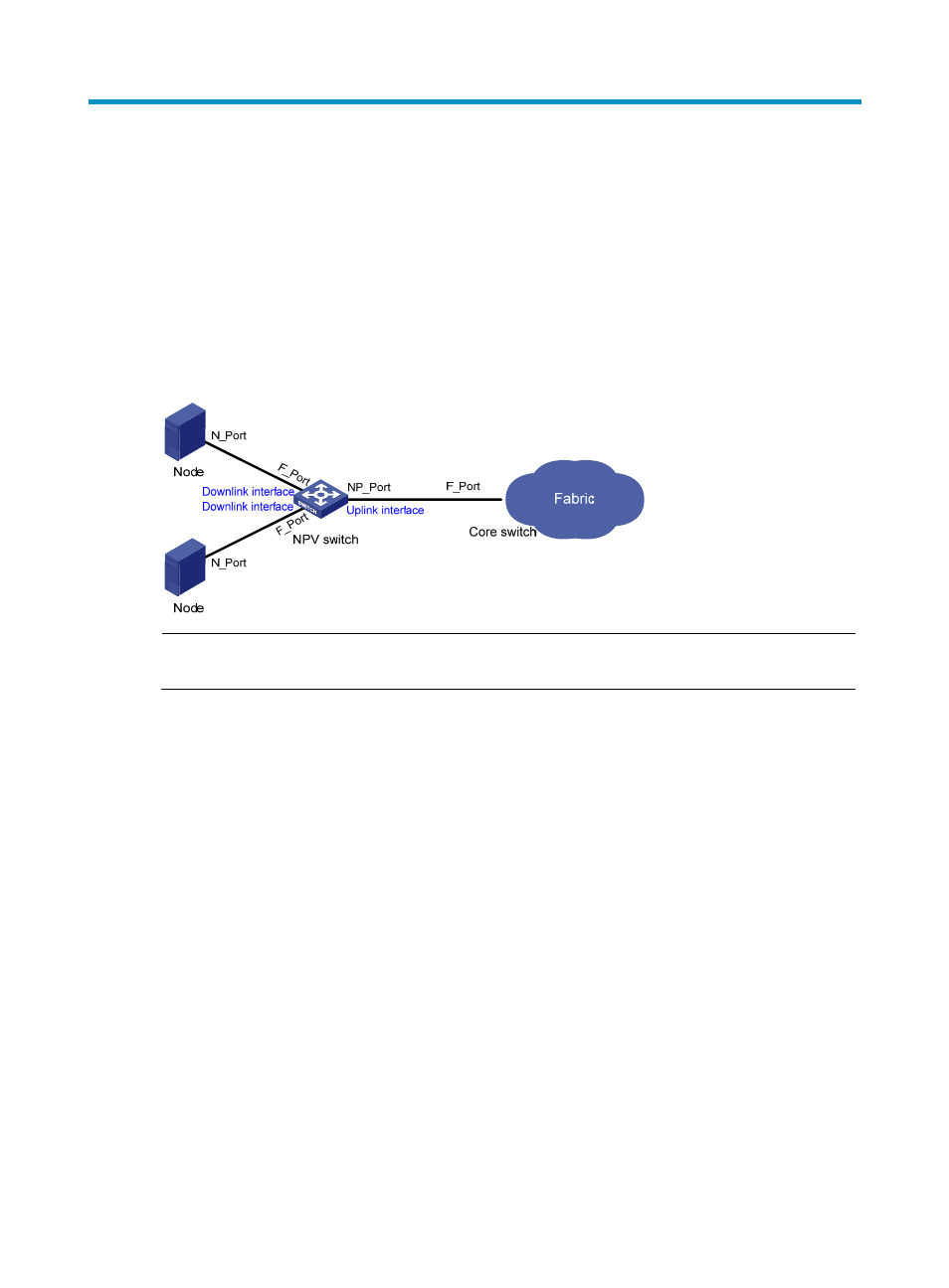
NPV switches forward traffic from nodes to the core switch.
shows a typical NPV network diagram.
Figure 28 NPV network diagram
NOTE:
An NPV switch must be directly connected to the core switch.
Downlink interface and downlink
A downlink interface, also known as a server interface, is an interface through which an NPV switch
connects to a node. It must be a VFC interface operating in F mode.
A downlink is a link from an NPV switch to its node.
Each downlink interface is uniquely mapped to an operational uplink interface. All traffic from the node
connected to the downlink interface is forwarded to the core switch through the uplink interface.
Uplink interface and uplink
An uplink interface, also known as an external interface, is the interface through which an NPV switch
connects to the core switch. It must be a VFC interface operating in NP mode.
An uplink is a link from an NPV switch to the core switch.
When the uplink becomes operational, the NPV switch sends a fabric login (FLOGI) packet to the core
switch for registration. The core switch assigns the uplink interface (NP_Port) an FC address. Then, the
NPV switch registers itself with the name server on the core switch. When receiving a packet from a node,
the NPV switch performs the following operations:
•
Forwards the packet to the core switch through the mapped uplink interface.