Requirements analysis – H3C Technologies H3C S10500 Series Switches User Manual
Page 155
144
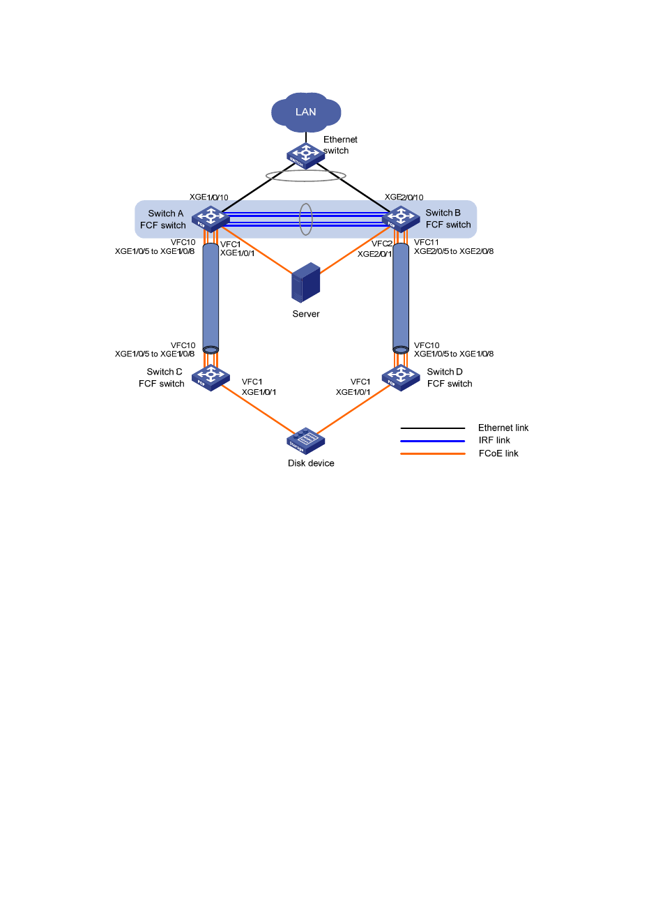
Figure 37 Network diagram
Requirements analysis
To uniformly manage Switch A and Switch B and implement backup between them, configure Switch A
and Switch B to form an IRF fabric. The IRF fabric uses Switch A as the master device. The IRF fabric
operates at the access layer of the LAN and operates as the FCF switch of the SANs.
To increase the bandwidth for the link between the IRF fabric and the Ethernet switch, aggregate the links
from the Ethernet switch to Switch A and Switch B.
To transmit the storage traffic over lossless Ethernet links in the SANs, perform the following tasks:
•
Configure DCBX, PFC in auto mode, and ETS on the Ethernet interfaces connecting the switches to
the server.
•
Configure DCBX and PFC in auto mode on the Ethernet interfaces connecting the switches to the
disk device.
•
Enable PFC by force on the Ethernet interfaces connecting switches.
To implement link backup between the server and the disk device, use two separate SANs to provide
connections between the server and the disk device. The two separate VSANs are as follows:
•
One physical SAN is formed by the server, the IRF fabric, Switch C, and the disk device.
•
The other physical SAN is formed by the server, the IRF fabric, Switch D, and the disk device.
Link aggr
egation 2
Link aggr
egation 1