Configuration procedure, Network requirements – H3C Technologies H3C S10500 Series Switches User Manual
Page 62
51
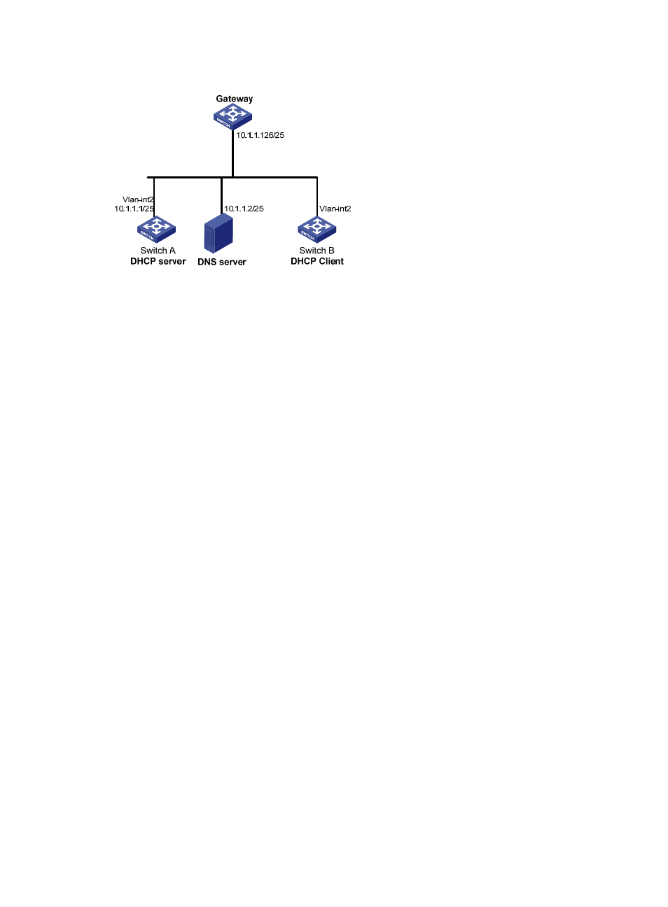
Figure 26 Network diagram for static IP address assignment
Configuration procedure
1.
Configure the IP address of VLAN-interface 2 on Switch A.
[SwitchA] interface vlan-interface 2
[SwitchA-Vlan-interface2] ip address 10.1.1.1 25
[SwitchA-Vlan-interface2] quit
2.
Configure the DHCP server
# Enable DHCP.
[SwitchA] dhcp enable
# Enable the DHCP server on VLAN-interface 2.
[SwitchA] interface vlan-interface 2
[SwitchA-Vlan-interface2] dhcp select server global-pool
[SwitchA-Vlan-interface2] quit
# Create DHCP address pool 0, configure a static binding, DNS server and gateway in it.
[SwitchA] dhcp server ip-pool 0
[SwitchA-dhcp-pool-0] static-bind ip-address 10.1.1.5
[SwitchA-dhcp-pool-0] static-bind client-identifier
3030-3066-2e65-3234-392e-3830-3530-2d56-6c61-6e2d-696e-7465-7266-6163-6532
[SwitchA-dhcp-pool-0] dns-list 10.1.1.2
[SwitchA-dhcp-pool-0] gateway-list 10.1.1.126
[SwitchA-dhcp-pool-0] quit
3.
Verification
After the preceding configuration is complete, Switch B can obtain IP address 10.1.1.5 and other network
parameters from Switch A. You can use the display dhcp server ip-in-use command on the DHCP server
to view the IP address assigned to the client.
Dynamic IP address assignment configuration example
Network requirements
•
As shown in
, the DHCP server (Switch A) assigns IP addresses to clients in subnet
10.1.1.0/24, which is subnetted into 10.1.1.0/25 and 10.1.1.128/25.