Gre over ipv6 tunnel configuration example, Network requirements, Configuration procedure – H3C Technologies H3C S10500 Series Switches User Manual
Page 202
191
10 packets output, 840 bytes
0 output error
# From Switch B, you can ping the IP address of VLAN-interface 100 on Switch A.
[SwitchB] ping 10.1.1.1
PING 10.1.1.1: 56 data bytes, press CTRL_C to break
Reply from 10.1.1.1: bytes=56 Sequence=1 ttl=255 time=2 ms
Reply from 10.1.1.1: bytes=56 Sequence=2 ttl=255 time=2 ms
Reply from 10.1.1.1: bytes=56 Sequence=3 ttl=255 time=2 ms
Reply from 10.1.1.1: bytes=56 Sequence=4 ttl=255 time=2 ms
Reply from 10.1.1.1: bytes=56 Sequence=5 ttl=255 time=2 ms
--- 10.1.1.1 ping statistics ---
5 packet(s) transmitted
5 packet(s) received
0.00% packet loss
round-trip min/avg/max = 2/2/2 ms
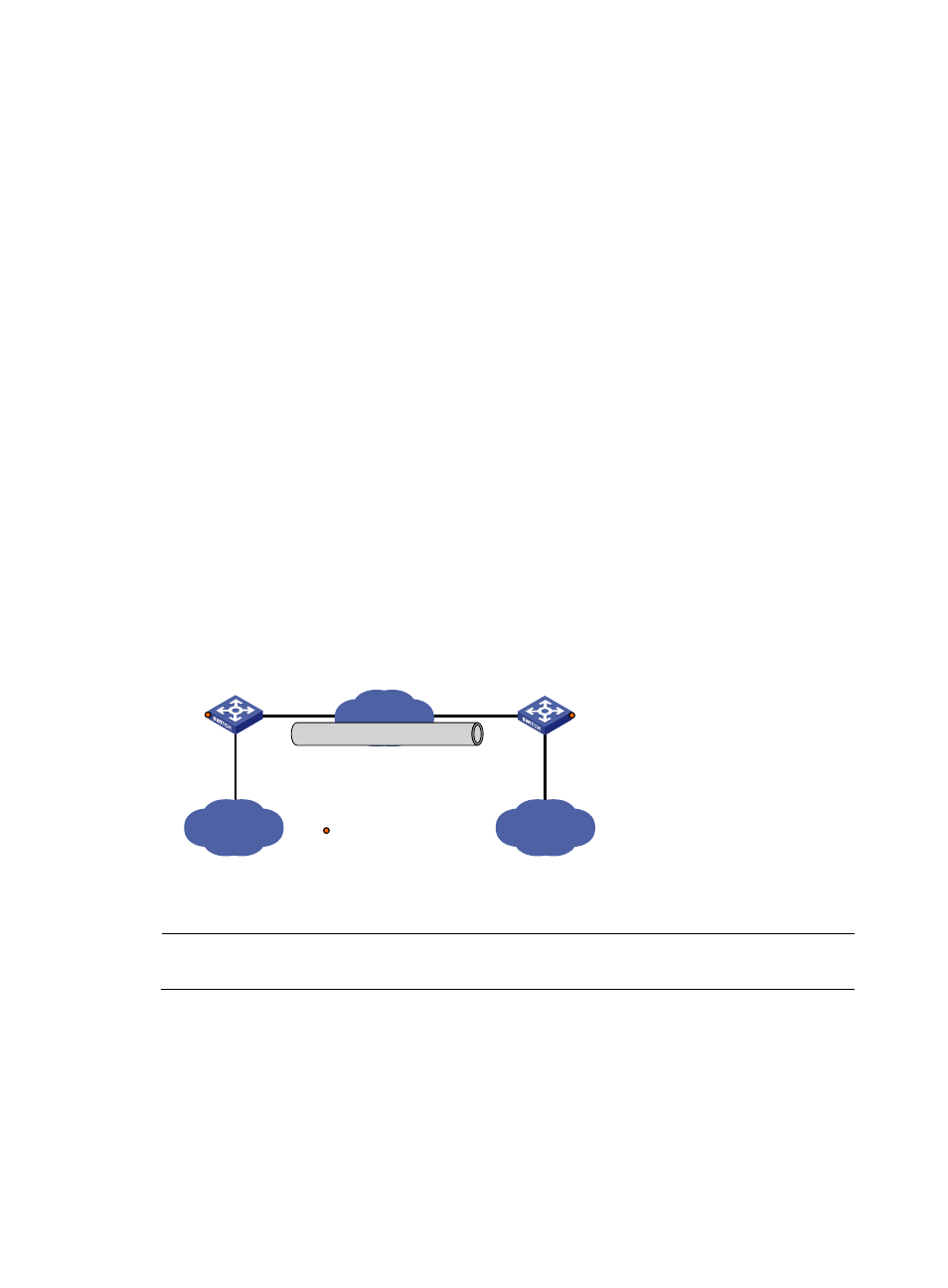
GRE over IPv6 tunnel configuration example
Network requirements
Two IPv4 subnets Group 1 and Group 2 are connected to an IPv6 network. Create a GRE over IPv6
tunnel between Switch A and Switch B, so that the two IPv4 subnets can communicate with each other
through the GRE tunnel over the IPv6 network.
Figure 80 Network diagram for a GRE over IPv6 tunnel
Vlan-int100
10.1.3.1/24
IPv4
Group 2
IPv4
Group 1
Vlan-int100
10.1.1.1/24
Tunnel0
10.1.2.1/24
Vlan-int101
2002::1:1/64
Vlan-int101
2001::2:1/64
IPv6 network
GRE tunnel
Tunnel0
10.1.2.2/24
Switch A
Switch B
Service loopback port
GE1/0/3
GE1/0/3
Configuration procedure
NOTE:
Before the configuration, make sure that Switch A and Switch B are reachable to each other.
1.
Configure Switch A
# Enable IPv6.
[SwitchA] ipv6
# Configure interface VLAN-interface 100.
[SwitchA] vlan 100
[SwitchA-vlan100] port GigabitEthernet 1/0/1