Configuration procedure, Network requirements – H3C Technologies H3C S10500 Series Switches User Manual
Page 29
18
Configuration procedure
# Create VLAN 2.
[Switch] vlan 2
[Switch-vlan2] quit
# Specify the IP address of interface VLAN-interface 1.
[Switch] interface vlan-interface 1
[Switch-Vlan-interface1] ip address 192.168.10.99 255.255.255.0
# Enable proxy ARP on interface VLAN-interface 1.
[Switch-Vlan-interface1] proxy-arp enable
[Switch-Vlan-interface1] quit
# Specify the IP address of interface VLAN-interface 2.
[Switch] interface vlan-interface 2
[Switch-Vlan-interface2] ip address 192.168.20.99 255.255.255.0
# Enable proxy ARP on interface VLAN-interface 2.
[Switch-Vlan-interface2] proxy-arp enable
After completing preceding configurations, use the ping command to verify the connectivity between
Host A and Host D.
Local proxy ARP configuration example in case of port isolation
Network requirements
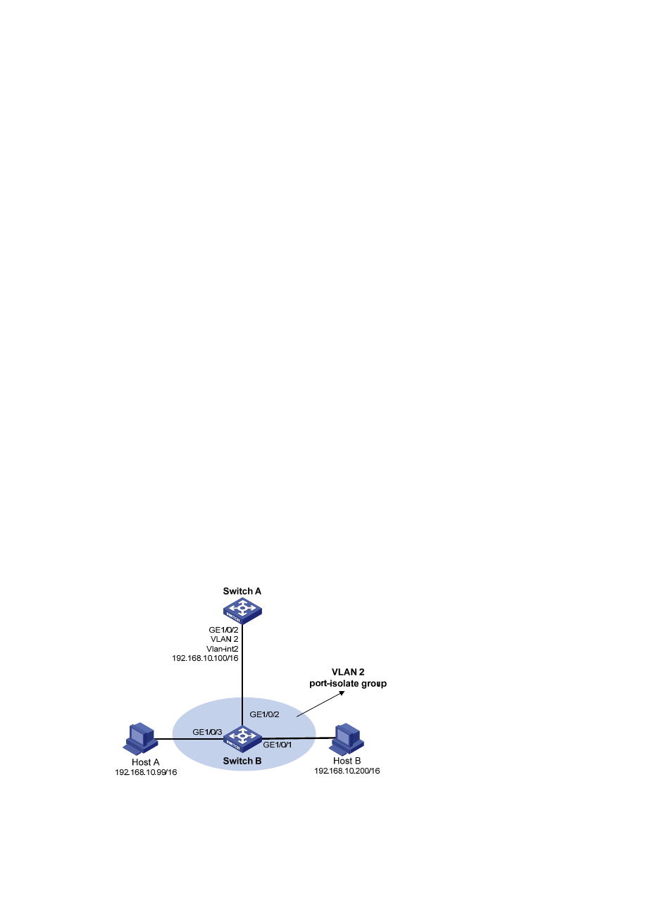
As shown in
, Host A and Host B belong to the same VLAN, and connect to Switch B via
GigabitEthernet 1/0/3 and GigabitEthernet 1/0/1 respectively. Switch B connects to Switch A via
GigabitEthernet 1/0/2.
Configure port isolation on GigabitEthernet 1/0/3 and GigabitEthernet 1/0/1 of Switch B to isolate
Host A from Host B at Layer 2. Enable local proxy ARP on Switch A to allow communication between
Host A and Host B at Layer 3.
Figure 10 Network diagram for local proxy ARP between isolated ports
Configuration procedure
1.
Configure Switch B