Configuration procedure – H3C Technologies H3C S10500 Series Switches User Manual
Page 199
188
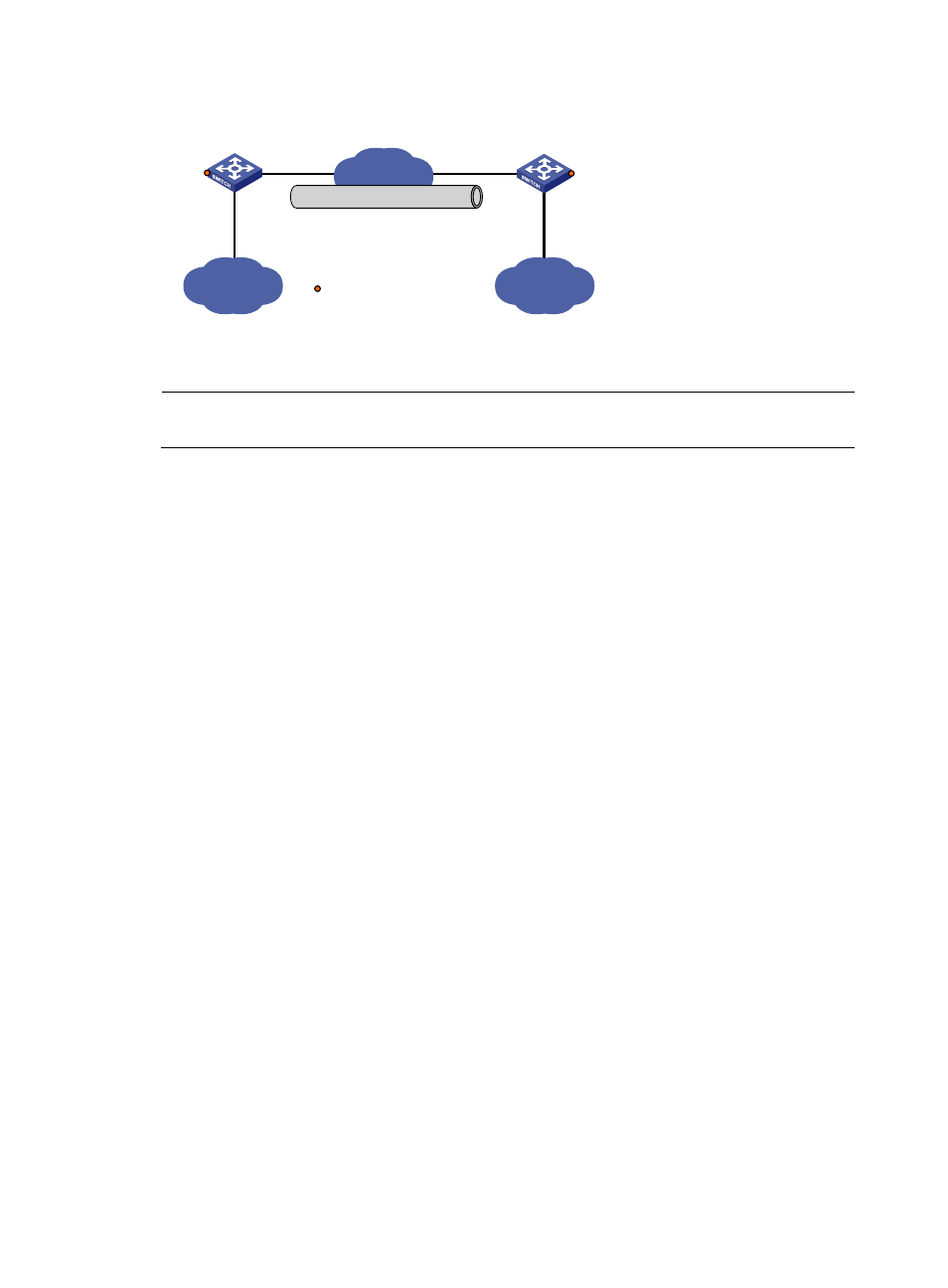
Figure 79 Network diagram for a GRE over IPv4 tunnel
IPv4
Group 2
IPv4
Group 1
Vlan-int100
10.1.1.1/24
Vlan-int100
10.1.3.1/24
Tunnel1
10.1.2.1/24
Vlan-int101
1.1.1.1/24
Vlan-int101
2.2.2.2/24
IPv4 network
GRE tunnel
Tunnel1
10.1.2.2/24
Switch A
Switch B
Service loopback port
GE1/0/3
GE1/0/3
Configuration procedure
NOTE:
Before the configuration, make sure that Switch A and Switch B are reachable to each other.
1.
Configure Switch A
# Configure an IPv4 address for interface GigabitEthernet 1/0/1.
[SwitchA] vlan 100
[SwitchA-vlan100] port GigabitEthernet 1/0/1
[SwitchA-vlan100] quit
[SwitchA] interface vlan-interface 100
[SwitchA-Vlan-interface100] ip address 10.1.1.1 255.255.255.0
[SwitchA-Vlan-interface100] quit
# Configure an IPv4 address for interface GigabitEthernet 1/0/2, the physical interface of the tunnel.
[SwitchA] vlan 101
[SwitchA-vlan101] port GigabitEthernet 1/0/2
[SwitchA-vlan101] quit
[SwitchA] interface vlan-interface 101
[SwitchA-Vlan-interface101] ip address 1.1.1.1 255.255.255.0
[SwitchA-Vlan-interface101] quit
# Create service loopback group 1, and configure the service type as tunnel.
[SwitchA] service-loopback group 1 type tunnel
# Add port GigabitEthernet 1/0/3 to service loopback group 1, and disable STP and LLDP on the port.
[SwitchA] interface GigabitEthernet 1/0/3
[SwitchA-GigabitEthernet1/0/3] undo stp enable
[SwitchA-GigabitEthernet1/0/3] undo lldp enable
[SwitchA-GigabitEthernet1/0/3] port service-loopback group 1
[SwitchA-GigabitEthernet1/0/3] quit
# Create a tunnel interface Tunnel 1.
[SwitchA] interface tunnel 1
# Configure an IPv4 address for interface Tunnel 1.
[SwitchA-Tunnel1] ip address 10.1.2.1 255.255.255.0
# Configure the tunnel encapsulation mode as GRE over IPv4.