Configuration procedure, Configuration example, Network requirements – H3C Technologies H3C S10500 Series Switches User Manual
Page 179
168
•
If you specify a source interface instead of a source address for the tunnel, the source address of the
tunnel is the primary IP address of the source interface.
Configuration procedure
Follow these steps to configure an IPv4 over IPv4 tunnel:
To do…
Use the command…
Remarks
Enter system view
system-view
—
Enter tunnel interface view
interface tunnel number —
Configure an IPv4 address for
the tunnel interface
ip address ip-address { mask |
mask-length } [ sub ]
Required
By default, no IPv4 address is
configured for the tunnel interface.
Specify the IPv4 over IPv4
tunnel mode
tunnel-protocol ipv4-ipv4
Optional
GRE over IPv4 tunnel by default.
The same tunnel mode should be
configured at both ends of the tunnel.
Otherwise, packet delivery will fail.
Configure a source address
or interface for the tunnel
interface
source { ip-address | interface-type
interface-number }
Required
By default, no source address or
interface is configured for the tunnel.
Configure a destination
address for the tunnel
interface
destination ip-address
Required
By default, no destination address is
configured for the tunnel.
Configuration example
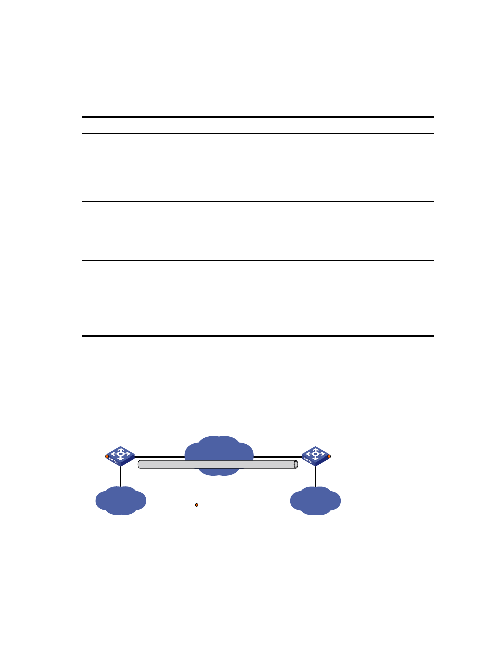
Network requirements
As shown in
, the two subnets Group 1 and Group 2 use private IPv4 addresses. Configure an
IPv4 over IPv4 tunnel between Switch A and Switch B to make the two subnets reachable to each other.
Figure 73 Network diagram for an IPv4 over IPv4 tunnel (on switches)
Vlan-int101
2.1.1.1/24
Vlan-int100
10.1.3.1/24
Vlan-int100
10.1.1.1/24
Switch A
IPv4 netwok
IPv4
Group 1
Tunnel1
10.1.2.1/24
Vlan-int101
3.1.1.1/24
Tunnel2
10.1.2.2/24
IPv4
Group 2
Switch B
IPv4 over IPv4 tunnel
Service loopback port
GE1/0/3
GE1/0/3
Configuration procedure
NOTE:
Before configuring an IPv4 over IPv4 tunnel, make sure that Switch A and Switch B have the corresponding
VLAN interfaces created and are reachable to each other.