Configuration procedure – H3C Technologies H3C S10500 Series Switches User Manual
Page 176
165
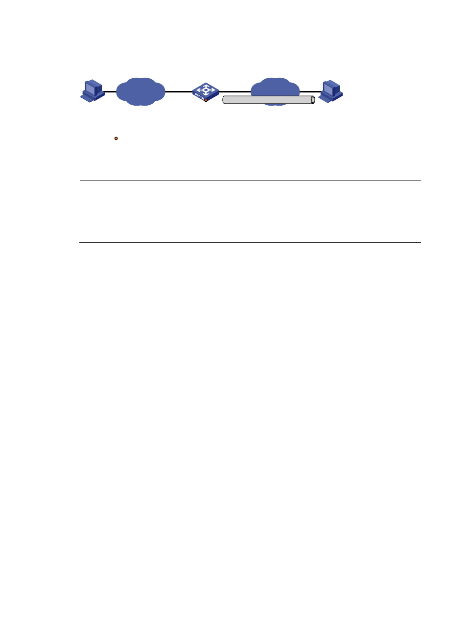
Figure 72 Network diagram for an ISATAP tunnel
IPv6 network
Vlan-int101
1.1.1.1/8
Vlan-int100
3001::1/64
Switch
ISATAP switch
IPv6 host
ISATAP host
IPv4 address:2.1.1.2/32
IPv6 address:
FE80::5EFE:0201:0102
2001::5EFE:0201:0102
3002::2/64
IPv4 network
Tunnel0
2001::5EFE:0101:0101/64
ISATAP tunnel
Service loopack port
GE1/0/3
Configuration procedure
NOTE:
•
Before configuring an ISATAP tunnel, make sure that the corresponding VLAN interfaces have been
created on the switch.
•
Make sure that VLAN-interface 101 on the ISATAP switch and the ISATAP host are reachable to each
other.
•
Configuration on the switch
# Enable IPv6.
[Switch] ipv6
# Configure addresses for interfaces.
[Switch] interface vlan-interface 100
[Switch-Vlan-interface100] ipv6 address 3001::1/64
[Switch-Vlan-interface100] quit
[Switch] interface vlan-interface 101
[Switch-Vlan-interface101] ip address 1.1.1.1 255.0.0.0
[Switch-Vlan-interface101] quit
# Create service loopback group 1 to support the tunnel service.
[Switch] service-loopback group 1 type tunnel
# Assign GigabitEthernet 1/0/3 to service loopback group 1, and disable STP and LLDP on the
interface.
[Switch] interface GigabitEthernet 1/0/3
[Switch-GigabitEthernet1/0/3] undo stp enable
[Switch-GigabitEthernet1/0/3] undo lldp enable
[Switch-GigabitEthernet1/0/3] port service-loopback group 1
[Switch-GigabitEthernet1/0/3] quit
# Configure an ISATAP tunnel.
[Switch] interface tunnel 0
[Switch-Tunnel0] ipv6 address 2001::5efe:0101:0101 64
[Switch-Tunnel0] source vlan-interface 101
[Switch-Tunnel0] tunnel-protocol ipv6-ipv4 isatap
# Disable the RA suppression so that hosts can acquire information such as the address prefix from the
RA message released by the ISATAP switch.
[Switch-Tunnel0] undo ipv6 nd ra halt