Verification, Multicast arp configuration example ii, Network requirements – H3C Technologies H3C S10500 Series Switches User Manual
Page 22: Configuration procedure
11
Verification
•
NLB load sharing: Enable the FTP server function of Server A and Server B. Host A and Host B send
requests to the virtual IP address and each of them logs in to a different server.
•
NLB redundancy: Disable the network interface card of Server A. Host A and Host B send requests
to the virtual IP address and both log in to the FTP server on Server B.
Multicast ARP configuration example II
Network requirements
As shown in
, a small data center uses Microsoft multicast-mode NLB. Two S10500 switches form
an IRF fabric. To enable the switches to cooperate with NLB, configure the following:
•
Use the interfaces on the EB, EA, or SE card of the switch to connect to the hosts and servers.
•
Add GigabitEthernet 1/4/0/2 and GigabitEthernet 2/4/0/3 into VLAN 10, and specify IP
address 16.1.1.1/24 for VLAN-interface 10.
•
Add GigabitEthernet 1/3/0/4 and GigabitEthernet 2/3/0/1 into VLAN 20, and specify IP
address 10.0.0.1/24 for VLAN-interface 20.
•
Disable the ARP entry check function so that the switch can learn dynamic ARP entries containing
multicast MAC addresses.
•
Configure a static multicast MAC address entry so that only interfaces GigabitEthernet 1/4/0/2
and GigabitEthernet 2/4/0/3 can receive multicast information.
•
Specify 10.0.0.1/24 as the default gateway of Host A and Host B.
•
Specify 16.1.1.1/24 as the default gateway of Server A and Server B.
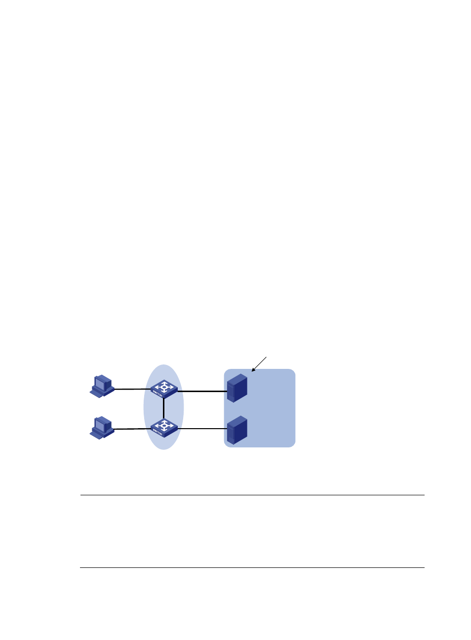
Figure 6 Network diagram for multicast ARP configuration II
Virtual IP : 16.1.1.100/24
Virtual MAC:03bf-1001-0164
Host A
IP:10.0.0.2/24
Server A
IP:16.1.1.18/24
Server B
IP:16.1.1.16/24
GE2/3/0/1
Host B
IP:10.0.0.3/24
GE1/4/0/2
GE1/3/0/4
IRF
GE2/4/0/3
Configuration procedure
NOTE:
•
This example only describes multicast ARP configuration. For more information about IRF, see the IRF
configuration guide for the S10500. For NLB configuration on the servers, see the related documents of
the Windows Server.
•
This configuration example assumes that the virtual IP address of Server A and Server B is 16.1.1.100/24,
and the virtual MAC address is 03bf-1001-0164.
•
Configure the switch