Configuration procedure – H3C Technologies H3C S12500 Series Switches User Manual
Page 183
172
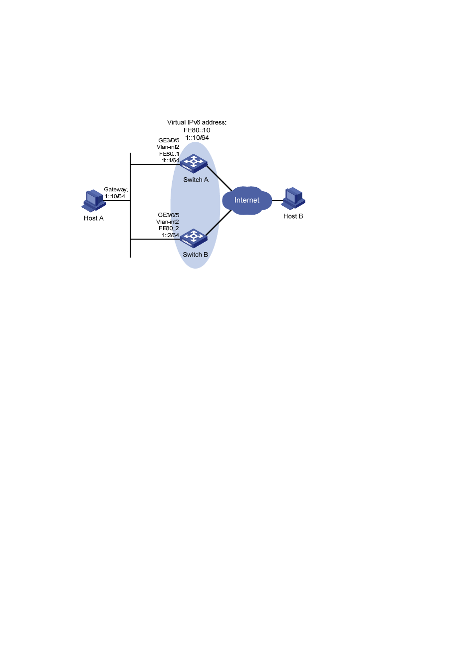
Host A wants to access Host B on the Internet, and learns 1::10/64 as its default gateway through RA
messages sent by the switches.
When Switch A operates correctly, packets sent from Host A to Host B are forwarded by Switch A; when
Switch A fails, packets sent from Host A to Host B are forwarded by Switch B.
Figure 43 Network diagram
Configuration procedure
1.
Configure Switch A:
# Configure VLAN 2.
[SwitchA] ipv6
[SwitchA] vlan 2
[SwitchA-vlan2] port Gigabitethernet 3/0/5
[SwitchA-vlan2] quit
[SwitchA] interface vlan-interface 2
[SwitchA-Vlan-interface2] ipv6 address fe80::1 link-local
[SwitchA-Vlan-interface2] ipv6 address 1::1 64
# Create a VRRP group 1 and set its virtual IPv6 addresses to FE80::10 and 1::10.
[SwitchA-Vlan-interface2] vrrp ipv6 vrid 1 virtual-ip fe80::10 link-local
[SwitchA-Vlan-interface2] vrrp ipv6 vrid 1 virtual-ip 1::10
# Set the priority of Switch A in VRRP group 1 to 110, which is higher than that of Switch B (100),
so that Switch A can become the master.
[SwitchA-Vlan-interface2] vrrp ipv6 vrid 1 priority 110
# Configure Switch A to operate in preemptive mode so that it can become the master whenever
it works correctly, and configure the preemption delay as 5 seconds to avoid frequent status
switchover.
[SwitchA-Vlan-interface2] vrrp ipv6 vrid 1 preempt-mode timer delay 5
# Enable Switch A to send RA messages, so that Host A can learn the default gateway address.
[SwitchA-Vlan-interface2] undo ipv6 nd ra halt
2.
Configure Switch B:
# Configure VLAN 2.