Configuration procedure – H3C Technologies H3C S12500 Series Switches User Manual
Page 167
156
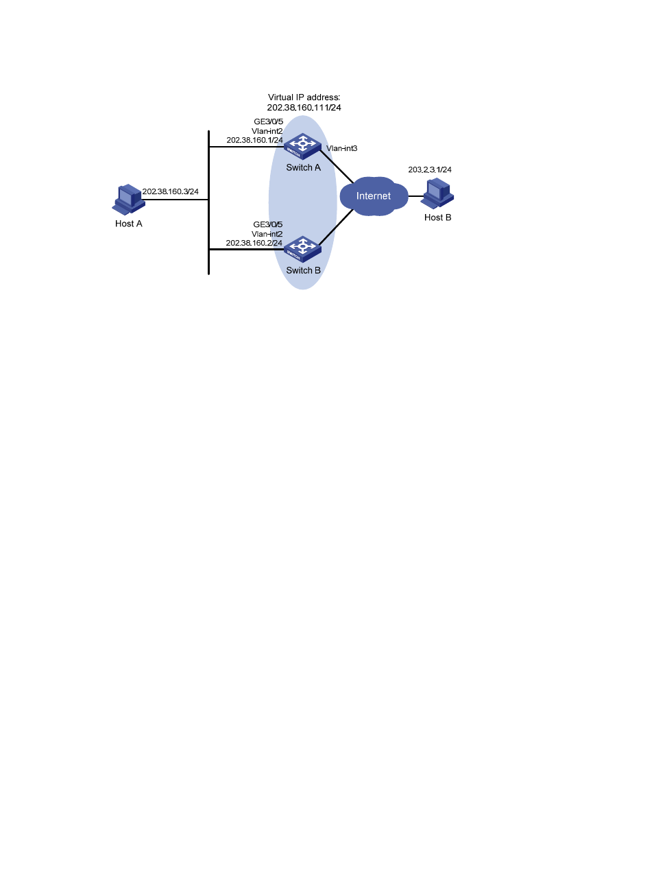
Figure 40 Network diagram
Configuration procedure
1.
Configure Switch A:
# Configure VLAN 2.
[SwitchA] vlan 2
[SwitchA-vlan2] port Gigabitethernet 3/0/5
[SwitchA-vlan2] quit
[SwitchA] interface vlan-interface 2
[SwitchA-Vlan-interface2] ip address 202.38.160.1 255.255.255.0
# Create a VRRP group 1 and set its virtual IP address to 202.38.160.111.
[SwitchA-Vlan-interface2] vrrp vrid 1 virtual-ip 202.38.160.111
# Configure the priority of Switch A in the VRRP group to 110, which is higher than that of Switch
B (100), so that Switch A can become the master.
[SwitchA-Vlan-interface2] vrrp vrid 1 priority 110
# Configure the authentication mode of the VRRP group as simple and authentication key as hello.
[SwitchA-Vlan-interface2] vrrp vrid 1 authentication-mode simple hello
# Set the interval for Master to send VRRP advertisement to 4 seconds.
[SwitchA-Vlan-interface2] vrrp vrid 1 timer advertise 4
# Configure Switch A to operate in preemptive mode, so that it can become the master whenever
it works correctly; configure the preemption delay as 5 seconds to avoid frequent status
switchover.
[SwitchA-Vlan-interface2] vrrp vrid 1 preempt-mode timer delay 5
# Set VLAN interface 3 on Switch A to be tracked, and configure the amount by which the priority
value decreases to be more than 10 (30 in this example), so that when VLAN-interface 3 fails, the
priority of Switch A in VRRP group 1 decreases to a value lower than 100 and thus Switch B can
become the master.
[SwitchA-Vlan-interface2] vrrp vrid 1 track interface vlan-interface 3 reduced 30
2.
Configure Switch B:
# Configure VLAN 2.
[SwitchB] vlan 2