Single vrrp group configuration example, Network requirements, Configuration procedure – H3C Technologies H3C S12500 Series Switches User Manual
Page 164
153
Single VRRP group configuration example
Network requirements
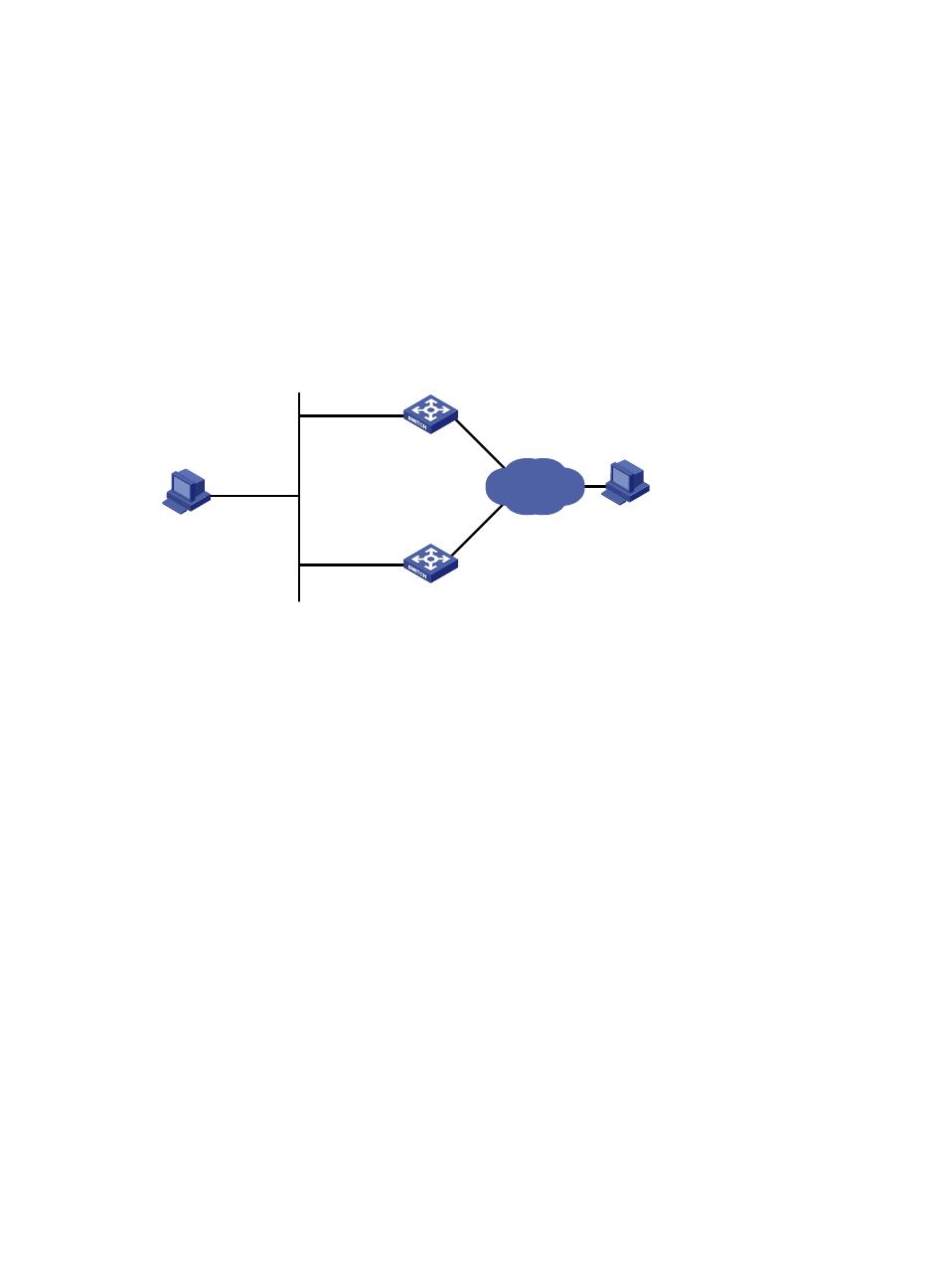
Host A wants to access Host B on the Internet, using 202.38.160.111/24 as its default gateway.
Switch A and Switch B belong to VRRP group 1 with the virtual IP address of 202.38.160.111/24.
When Switch A operates correctly, packets sent from Host A to Host B are forwarded by Switch A; when
Switch A fails, packets sent from Host A to Host B are forwarded by Switch B.
Figure 39 Network diagram
Configuration procedure
1.
Configure Switch A:
# Configure VLAN 2.
[SwitchA] vlan 2
[SwitchA-vlan2] port gigabitethernet 3/0/5
[SwitchA-vlan2] quit
[SwitchA] interface vlan-interface 2
[SwitchA-Vlan-interface2] ip address 202.38.160.1 255.255.255.0
# Create VRRP group 1 and set its virtual IP address to 202.38.160.111.
[SwitchA-Vlan-interface2] vrrp vrid 1 virtual-ip 202.38.160.111
# Set the priority of Switch A in VRRP group 1 to 110, which is higher than that of Switch B (100),
so that Switch A can become the master.
[SwitchA-Vlan-interface2] vrrp vrid 1 priority 110
# Configure Switch A to operate in preemptive mode so that it can become the master whenever
it works correctly, and configure the preemption delay as 5 seconds to avoid frequent status
switchover.
[SwitchA-Vlan-interface2] vrrp vrid 1 preempt-mode timer delay 5
2.
Configure Switch B:
# Configure VLAN 2.
[SwitchB] vlan 2
[SwitchB-Vlan2] port Gigabitethernet 3/0/5
Host A
Switch A
Switch B
Virtual IP address:
202.38.160.111/24
GE3/0/5
Vlan-int2
202.38.160.1/24
GE3/0/5
Vlan-int2
202.38.160.2/24
Host B
202.38.160.3/24
203.2.3.1/24
Internet