Smart link configuration examples, Single smart link group configuration example, Network requirements – H3C Technologies H3C S12500 Series Switches User Manual
Page 122: Configuration procedure
111
Task Command
Remarks
Display information about the
received flush messages.
display smart-link flush [ | { begin
| exclude | include }
regular-expression ]
Available in any view.
Clear the statistics about flush
messages.
reset smart-link statistics
Available in user view.
Smart Link configuration examples
IMPORTANT:
By default, Ethernet, VLAN, and aggregate interfaces are in DOWN state. Before configuring these
interfaces, use the undo shutdown command to bring them up.
Single Smart Link group configuration example
Network requirements
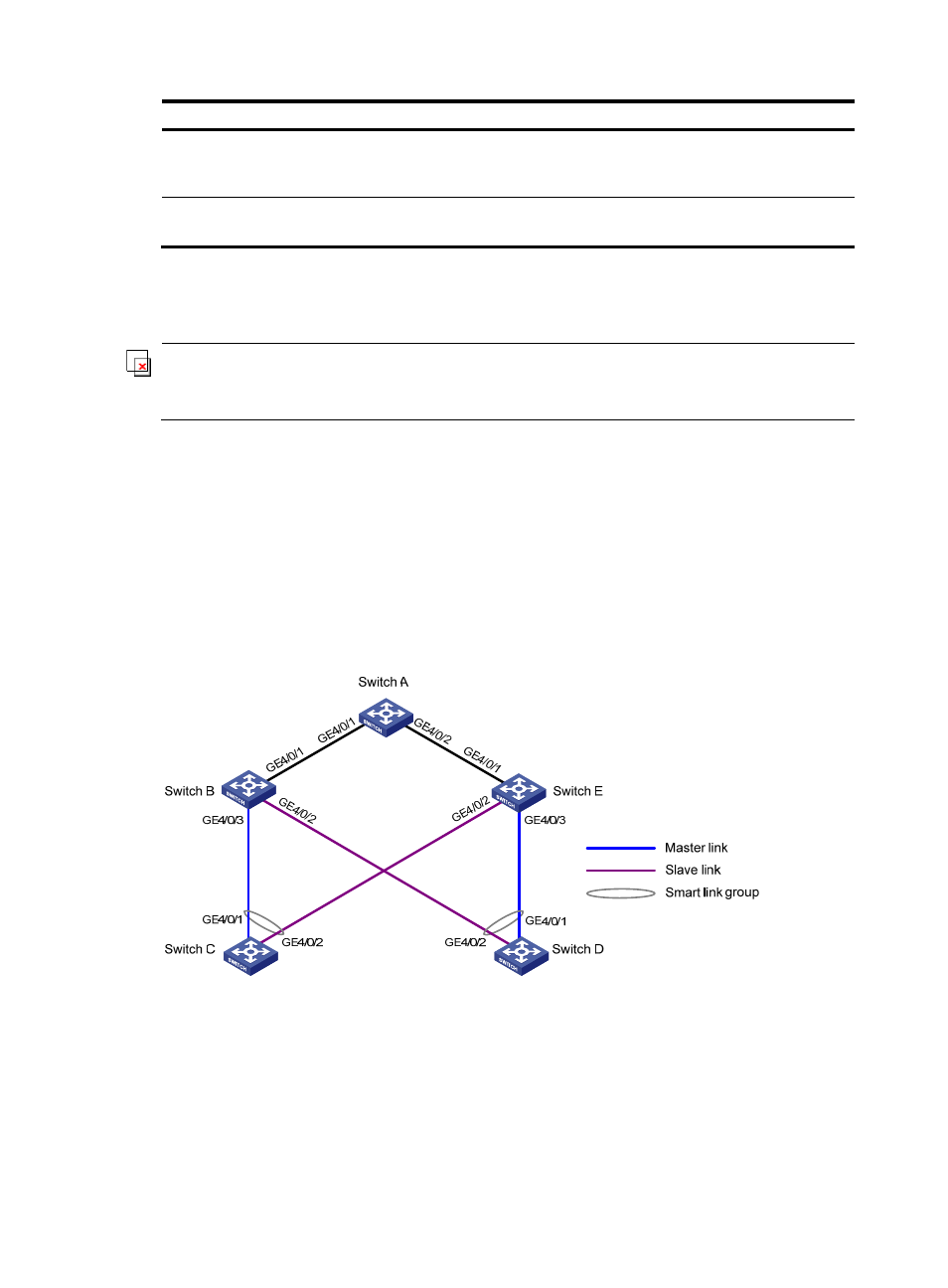
As shown in
, Switch C and Switch D are smart link devices, and Switch A, Switch B, and Switch
E are associated devices. Traffic of VLANs 1 through 30 on Switch C and Switch D are dually uplinked
to Switch A.
Configure Smart Link on Switch C and Switch D for dual uplink backup.
Figure 24 Network diagram
Configuration procedure
1.
Configure Switch C:
# Create VLANs 1 through 30, map these VLANs to MSTI 1, and activate the MST region
configuration.
[SwitchC] vlan 1 to 30
[SwitchC] stp region-configuration