Super Systems 20Q User Manual
Page 16
12
+
_
_____
+
24
25
OUT 1
SOLID STATE
RELAY
+
_
_____
+
27
28
OUT 2
SOLID STATE
RELAY
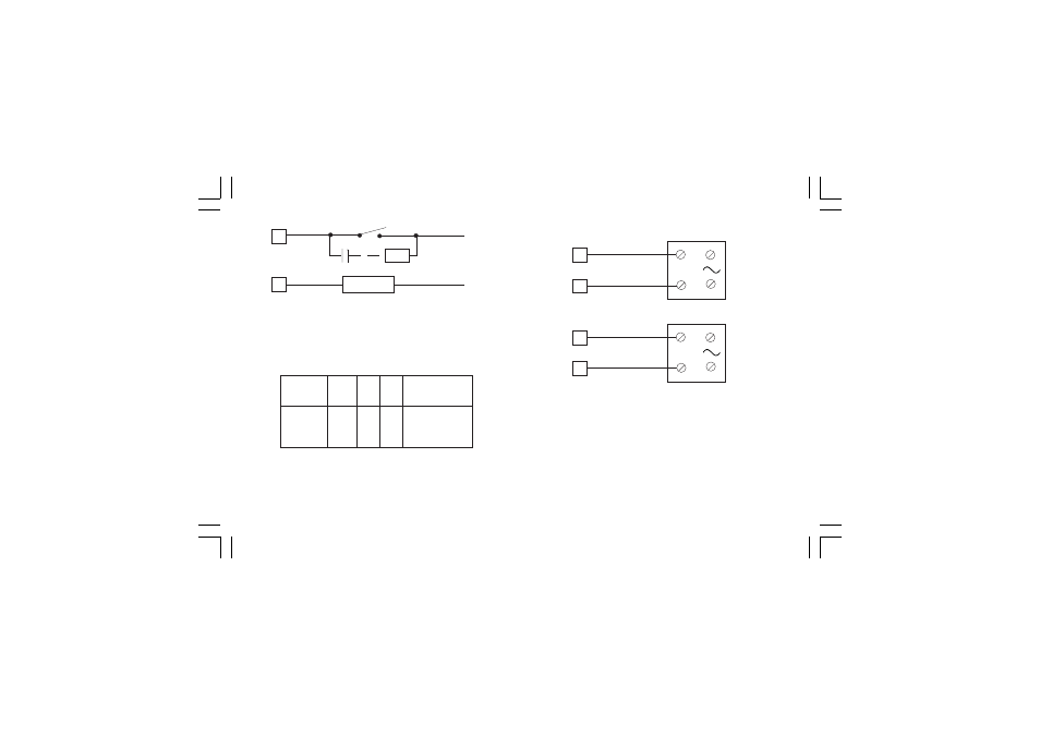
Fig. 12 EXTERNAL SWITCH IN SERIES WITH THE INTERNAL
CONTACT
In this case it is recommended to install an additional RC
network across the external contact as show in Fig. 12
The value of capacitor (C) and resistor (R) are shown in the
following table.
Anyway the cable involved in relay output wiring must be as far
away as possible from input or communication cables.
E.2) VOLTAGE OUTPUTS FOR SSR DRIVE
E.2) VOLTAGE OUTPUTS FOR SSR DRIVE
E.2) VOLTAGE OUTPUTS FOR SSR DRIVE
E.2) VOLTAGE OUTPUTS FOR SSR DRIVE
E.2) VOLTAGE OUTPUTS FOR SSR DRIVE
Fig. 13 SSR DRIVE OUTPUT WIRING
Logic level 0
Logic level 0
Logic level 0
Logic level 0
Logic level 0: Vout < 0.5 V DC.
Logic level 1
Logic level 1
Logic level 1
Logic level 1
Logic level 1:
- 14 V + 20 % @ 20 mA
- 24 V + 20 % @ 1 mA.
Maximum current = 20 mA.
NOTE
NOTE
NOTE
NOTE
NOTE: This output is not isolated.
A double or reinforced insulation between instrument output and
power supply must be assured by the external solid state relay.
LOAD
(mA)
<40 mA
<150 mA
<0.5 A
C
(
µ
F)
0.047
0.1
0.33
R
(
Ω
)
100
22
47
P.
(W)
1/2
2
2
OPERATING
VOLTAGE
260 V AC
260 V AC
260 V AC
R
C
LOAD
LINE
mkc-ssi.pmd
06/07/2004, 12.19
12