Ples, Ä chapter 4.3 ‘template hydraulic dia, Grams with installation parameters – REMKO WPM-Smart-Control-Manual for specialists-WKF-120 User Manual
Page 49
4.3
Template hydraulic diagrams with installation parameters
NOTICE!
The following template hydraulic systems are only to be used as a planning aid, and do not replace an
installation drawing! Technical modifications reserved!
The design and planning of customer-provided hydraulic systems must be performed by a specialist
installer!
We recommend adapting plant-specific parameters, such a heating limits and bivalence point, to the
design data!
You can find further hydraulics examples at www.remko.de
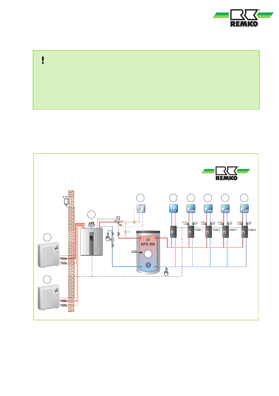
Hydraulic diagram for heat pump assembly WKF Köln
Functions: Heating or cooling, operating mode: monoenergetic or bivalent alternative
Only one cycle is possible for cooling; active cooling or floor heating (passive cooling)
The operating mode here can only be monoenergetic or bivalent alternative!
A1
B
E
D
A2
F
1
F
2
F
3
F
4
C
Fig. 87: Example hydraulic diagram for HP assembly WKF Köln
A1:
Outdoor unit 1
A2:
Outdoor unit 2 (WKF Duo)
B:
Indoor unit (WKF/WKF Duo)
C:
Storage tank
D:
Second heat generator
E:
Cooling cycle
F1-2:
Mixed heating cycle (WKF)
F1-4:
Mixed heating cycle (WKF Duo)
49