3 serial cable wiring diagrams – Measurement Computing Micro 488/EX rev.2.1 User Manual
Page 30
Section 2
Getting Started
2.16
Vtest
Test Voltage - Output - Pin 9
This pin is connected to 5 volts through a 1K
Ω resistor. It is also
common to Vtest on pin 6.
+RxD
Receive Data Plus - Input - Pin 14
This pin accepts serial data sent by the RS-422 host. The serial data
is expected with the word length, baud rate, stop bits and parity
selected by the internal switches. The signal level is high true and
only connected to this pin when RS-422 operation is selected. It is
180° out of phase with -RxD.
+TxD
Transmit Data Plus - Output - Pin 16
This pin transmits serial data to the RS-422 host. The serial data is
sent with the word length, baud rate, stop bits and parity selected by
the internal switches. The signal level is high true and only connected
to this pin when RS-422 operation is selected. It is 180° out of phase
with -TxD.
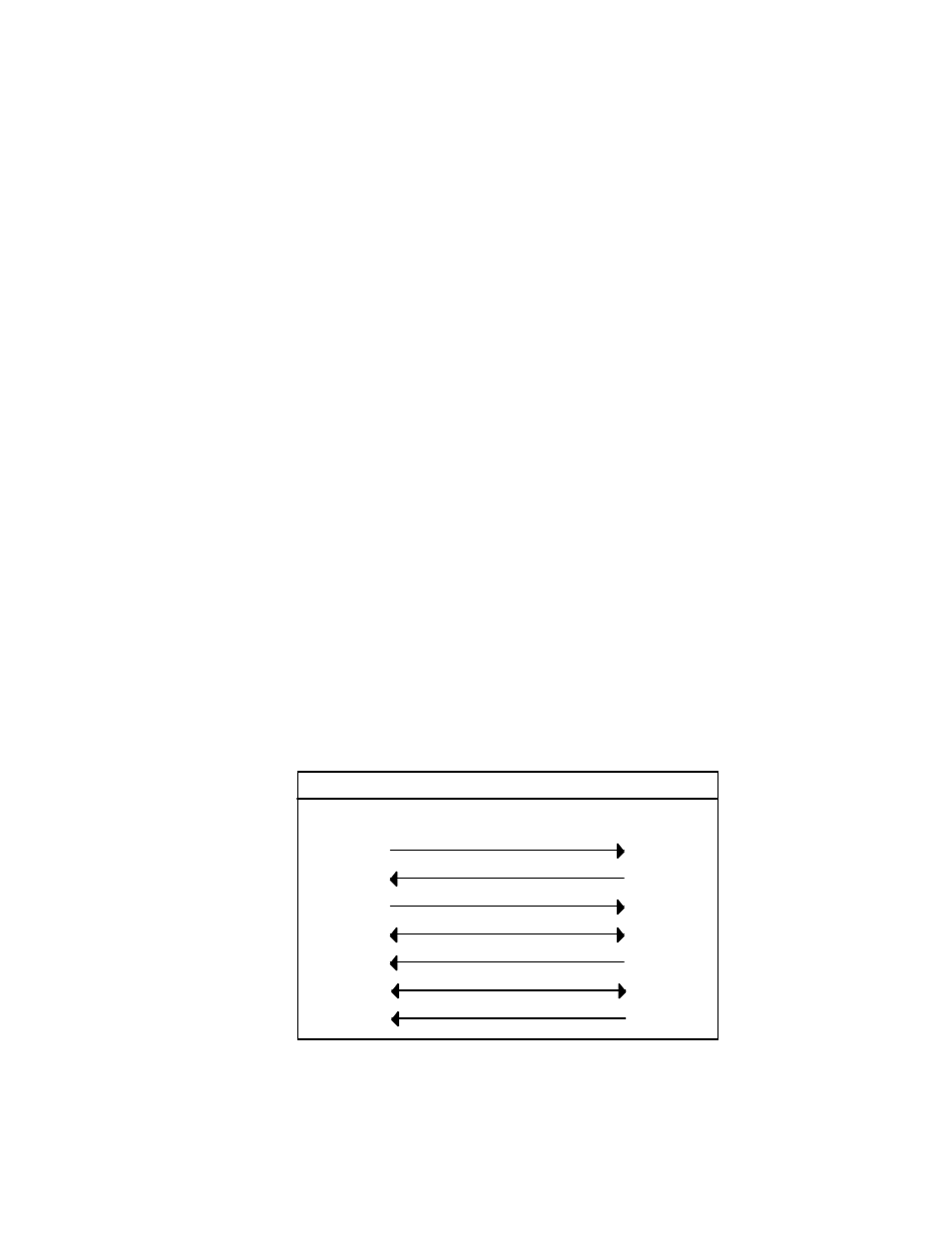
2.8.3 Serial Cable Wiring Diagrams
If a cable was not purchased with the interface, the following diagrams
will be helpful in making your own cable. Simple soldering skills and an
attention to detail will ensure successful construction.
Macintosh to Micro488/EX Wiring Diagram (RS-422)
6
7
5
3
9
4
5
2
7
3
CTS
RTS
-RxD
Gnd
-Txd
CTS
RTS
-RxD
Gnd
-TxD
DB-9 Male
DB-25 Male
Macintosh to Micro488/EX
4
14 +Rxd
+TxD
8
16 +Txd
+RxD