6 printer applications – Measurement Computing Micro 488/EX rev.2.1 User Manual
Page 170

Section 6
Controller Pass-Thru Operation
6.6
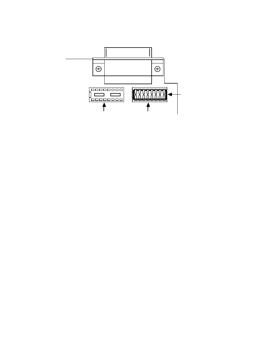
Selecting RS-232 Signal Levels
J205
J206
RS-422
RS-232
Shorting Plug
After configuration, turn on the plotter and the Micro488/EX. The Micro488/EX's
front panel LEDs should all light momentarily while it performs an internal ROM and
RAM test. All LEDs should go out except for the Power and Talk LED. The Talk LED
indicates that the Micro488/EX has detected the plotter on the IEEE bus and has
addressed it to listen.
When the serial host begins to send the Micro488/EX data, the Receive LED will
flash. If it does not, this indicates that the interface is not receiving data from the serial
host. Verify the cables are connected properly and the serial cable wiring. Verify the
serial data format, word length, stop bits and parity.
6.6 Printer Applications
Most of the information given for plotter applications applies to applications for
interfacing IEEE 488 printers to a serial host. Some high end printers have a secondary
command setting which must be disabled for the Micro488/EX to control them. The
Micro488/EX does not use secondary commands to control IEEE peripherals, such as
printers or plotters. Refer to the printer's instruction manual if the is a question as to
whether the printer requires secondary commands.
