100 amp, Operation, Pac186 mild steel o – Hypertherm HD3070 Plasma Arc Cutting System w/ Automatic Gas Console User Manual
Page 123: Plasma / o, Shield 100 amp cutting
4-34
HD3070 with Automatic Gas Console
Instruction Manual
16
OPERATION
Material
Thickness
(in)
(mm)
Arc
Voltage
(volts)
Torch
Standoff**
(in)
(mm)
Travel
Speed
(ipm)
(m/min)
Pierce
Delay
(dial)
(sec)
Initial
Piercing
Height
(in)
(mm)
1/8
3.2
10
100
35
90
60
–
137
0.125
3.2
275
7.0
0.180
4.6
0
0.00
1/4
6.4
10
100
35
90
60
–
141
0.125
3.2
135
3.43
0.300
7.6
0.4
0.22
3/8
9.5
10
100
35
90
60
–
145
0.125
3.2
95
2.41
0.300
7.6
0.7
0.27
1/2
12.7
10
100
35
90
60
–
147
0.125
3.2
64
1.62
0.300
7.7
1.0
0.37
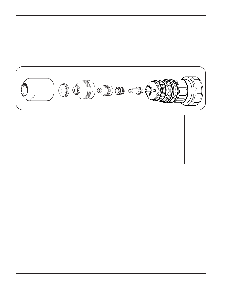
Shield
120273
Nozzle
120272
Electrode
120410
Retaining Cap
120266
Swirl Ring
020637
PAC186 Torch
120349
Shield Cap
020634/020687
PAC186
Mild Steel
O
2
Plasma / O
2
& N
2
Shield
100 Amp Cutting
O
2
and N
2
gas inlet pressures must be between 105 - 135 psi (7.2 - 9.2 bar) for all material thickness.
#
Refer to LCD display Figure 4-3.
* Slightly increasing the test preflow O
2
and N
2
flowrates may increase piercing capability on the thicker materials listed
above. However, increasing the preflow flowrates too much may affect plasma starting reliability (misfiring).
** Torch standoff tolerances are ± 0.005 inch (± 0.125 mm). When using a THC, tolerances are ± 1 volt.
Counter clockwise (CCW) consumables are available for mirror image cutting. Refer to Section 6, Parts List.
If problems occur with the cutting process, and the flowrates are suspect, refer to Section 5, Maintenance, Gas System Back
Pressure Checks.
Test Cut
Flowrates (%)
Shield
O
2
N
2
(3)
#
(4)
#
Plasma
O
2
(5)
#
(6)
#
Test Preflow*
Flowrates (%)
Preflow
O
2
N
2
(1)
#
(2)
#