50 amp, Operation pac186 copper## o, Plasma / o – Hypertherm HD3070 Plasma Arc Cutting System w/ Automatic Gas Console User Manual
Page 118: Shield 50 amp cutting
HD3070 with Automatic Gas Console
Instruction Manual
4-29
16
OPERATION
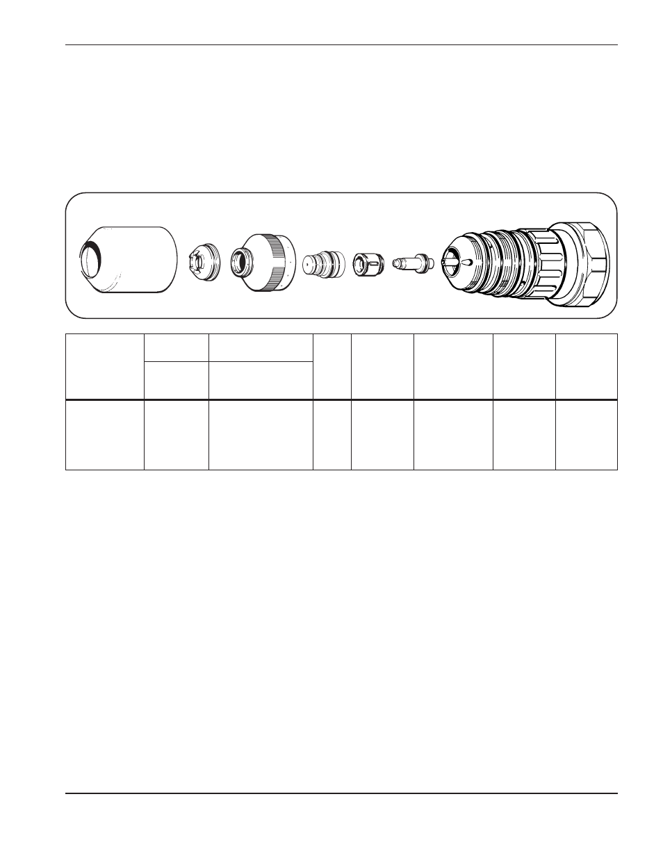
PAC186
Copper##
O
2
Plasma / O
2
& N
2
Shield
50 Amp Cutting
Shield
020949
Nozzle
020948
Electrode
120113
Retaining Cap
020795
Swirl Ring
020947
PAC186 Torch
120349
Shield Cap
020634/020687
Material
Thickness
(GA)
(in)
(mm)
Arc
Voltage
(volts)
Torch
Standoff**
(in)
(mm)
Travel
Speed
(ipm)
(m/min)
Pierce
Delay
(dial)
(sec)
Initial
Piercing
Height
***
(in)
(mm)
16
0.060
1.5
35
40
20
10
40
–
92
0.080
2.0
70
1.78
0.100
2.5
4
1.0
14
0.075
1.9
35
40
20
10
40
–
92
0.080
2.0
70
1.78
0.100
2.5
4
1.0
12
0.105
2.7
35
40
20
10
40
–
94
0.080
2.0
65
1.65
0.100
2.5
7
1.5
10
0.135
3.4
35
40
20
10
40
–
94
0.080
2.0
65
1.65
0.100
2.5
9
2.0
O
2
and N
2
gas inlet pressures must be between 105 - 135 psi (7.2 - 9.2 bar) for all material thickness.
#
Refer to LCD display Figure 4-3.
##
Copper plate sometimes comes with a protective plastic film. Remove film prior to cutting.
* Slightly increasing the test preflow O
2
and N
2
flowrates may increase piercing capability on the thicker materials listed
above. However, increasing the preflow flowrates too much may affect plasma starting reliability (misfiring).
** Torch standoff tolerances are ± 0.005 inch (± 0.125 mm). When using a THC, tolerances are ± 1 volt.
*** Measured from tips of shield adapter 020949.
Counter clockwise (CCW) consumables are available for mirror image cutting. Refer to Section 6, Parts List.
If problems occur with the cutting process, and the flowrates are suspect, refer to Section 5, Maintenance, Gas System Back
Pressure Checks.
Test Cut
Flowrates (%)
Shield
O
2
N
2
(3)
#
(4)
#
Plasma
O
2
(5)
#
(6)
#
Test Preflow*
Flowrates (%)
Preflow
O
2
N
2
(1)
#
(2)
#