A.3.2 connector pinouts – Comtech EF Data CLO-10 User Manual
Page 90
CLO-10 Link Optimizer
Revision 1
Redundant System Operation
MN/CLO-10.IOM
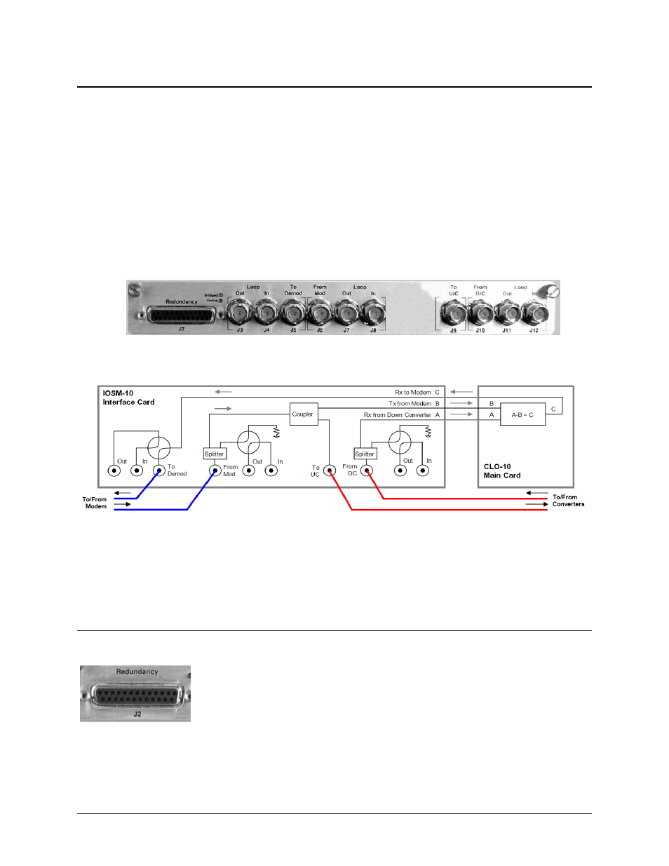
A.3.1.2 Overview: CLO-10 With Input/Output Switch Module (IOSM)
The CLO-10 with the Input/Output Switch Module (IOSM) can be used in two different
configurations:
• As a Standalone Traffic Unit (without Daisy Chain Redundancy).
Note: The J3, J4, J6, J7, J10, and J11 connectors are not used in this mode.
• As a Traffic Unit, from 1 up to 12 (as part of the Daisy Chain Redundancy).
Figure A-5 shows the IOSM; Figure A-6 shows the functional block diagram of the IOSM as it
operates in tandem with the CLO-10 Main Card (installed in the CLO-10 chassis).
Figure A-6. IOSM (CEFD P/N PL/12834-1)
Figure A-7. CLO-10 With IOSM – Block Diagram
A.3.2 Connector Pinouts
A.3.2.1 IOM / IOSM Redundancy Connector, J2 (DB-25F)
Typical for both the IOM and IOSM, the J2 Redundancy connector is a Type ‘D’
25-pin female connector used to connect the CLO-10 to other CLO-10s in the
optional Daisy Chain Redundancy system via the High Speed Bus (HSB) Cable
(CEFD P/N CA/RB0014-XX-U2). This cable is used to communicate between the
CLO-10-1 Redundant (controller) Unit and CLO-10-2 Traffic Unit(s).
A–6