Comtech EF Data CLO-10 User Manual
Page 100
CLO-10 Link Optimizer
Revision 1
Redundant System Operation
MN/CLO-10.IOM
► To replace a faulted Traffic Unit that is being backed up by the Redundant Unit:
•
•
CAUTION
Do not deactivate this unit, as the Traffic path must be maintained.
Step
Procedure
1
Power-down the unit.
2
Loosen the thumb screws securing the module to the chassis. Do not unplug the
cable connections.
3
Remove the module from the chassis slot by sliding the module straight out until it
is clear of the chassis.
NOTE: It is recommended that the unit being replaced is first pushed a few
inches towards the front to the rack/cabinet in order to provide slack for the
installed HSB cable, thus easing removal of the still-cabled module.
See Figure A-15.
4
Swap out the faulted unit with the replacement CLO-10 unit.
5
Re-install the module into the replacement CLO-10 unit by inserting the module
straight into
the chassis slot, using the chassis’ internal card guides.
6
Secure the module to the replacement unit using the captive thumb screws.
7
Configure the unit as outlined in Chapter 4. MODEM AND OPTIMIZER
CONFIGURATION.
►
The new Traffic Unit should lock as it is bridging the Redundant Unit. The system
will then be ready and able to cope with any other fault that may occur.
►
If desired, the user can go to AUTO-OFF (manual operation) mode, switch over
the active Traffic from the Redundant CLO-10 onto the Traffic CLO-10, and then
return to AUTO-ON (automatic operation) mode.
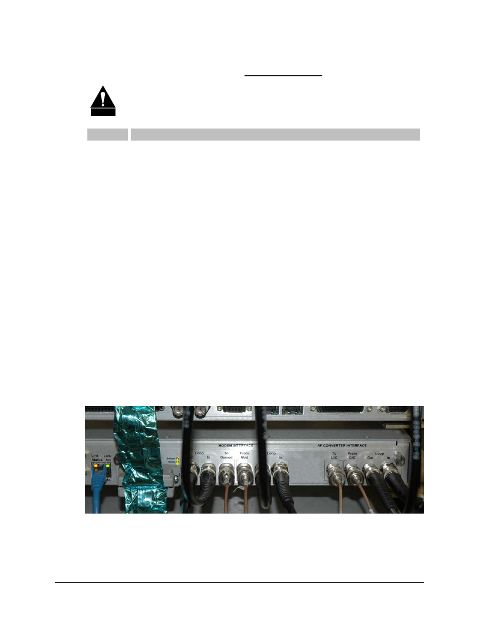
Figure A-13. Operating Configuration
A–16