4 standard logical device configuration register, Table 6-2, Standard configuration register map – Artesyn MITX-CORE-820 Installation and Use (July 2014) User Manual
Page 105: Firmware
Firmware
MITX-CORE-820 Installation and Use (6806800M10H)
105
6.2.4
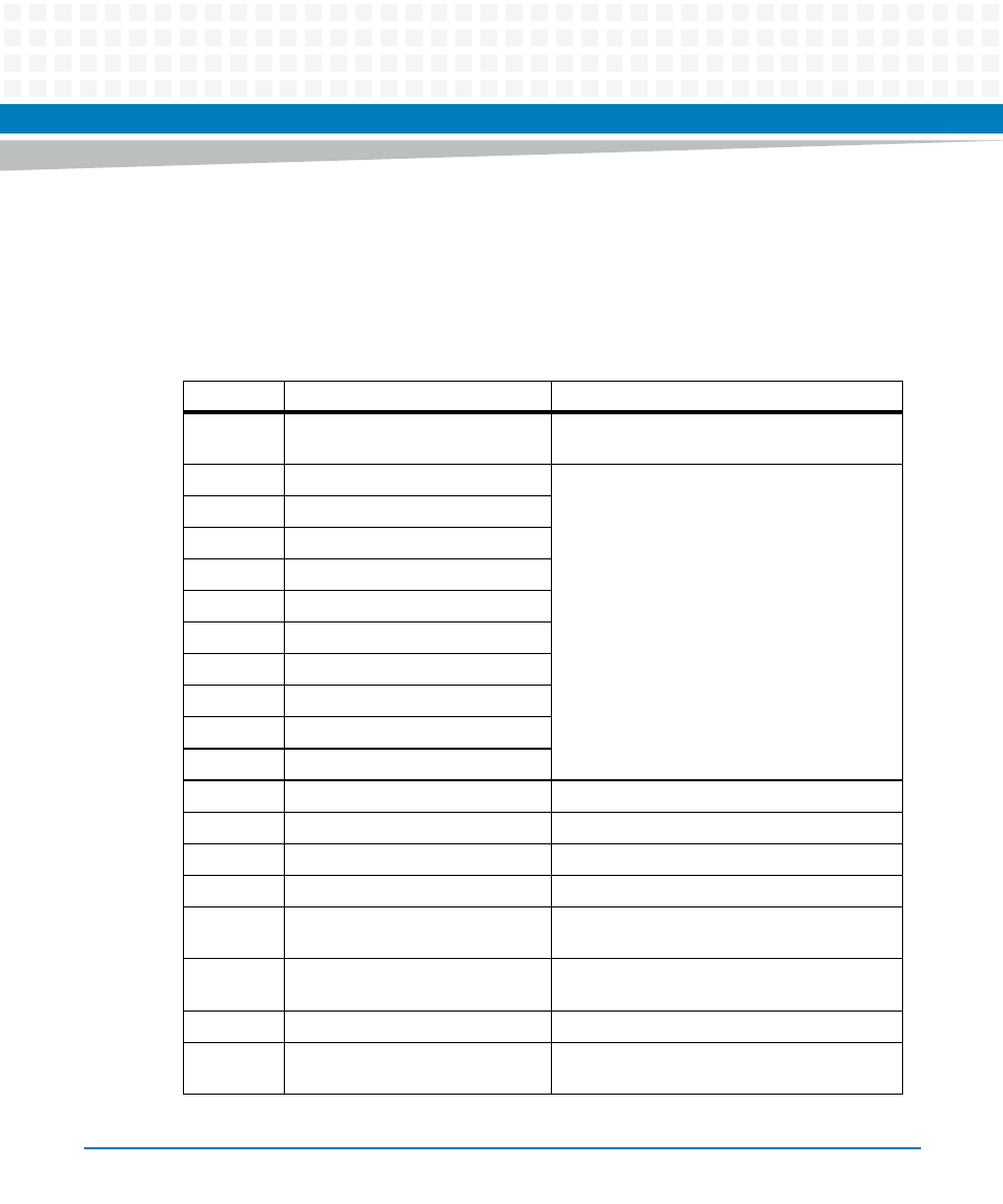
Standard Logical Device Configuration Register
All the standard logical device configuration registers can be accessed by the host processor
after reset. All registers are read/write enabled. The following table shows the detailed
definition of standard logical device configuration registers.
Table 6-2 Standard Configuration Register Map
Index
Register Name
Description
07h
Logical Device Number
This register selects the current logical device
number.
20h
Super I/O ID
Super I/O configuration register and ID
registers
21h
Super I/O Configuration 1
24h
Super I/O Chip Revision
25h
Super I/O Configuration 5
26h
Super I/O Configuration 6
27h
Super I/O Revision ID
28h
Super I/O General Purpose Scratch
29h
Super I/O Configuration 9
2Dh
Super I/O Configuration D
2Eh - 2Fh
Reserved for Nuvoton use
30h
Logical Device Control (Activate)
Enable or disable the logical device
60h - 61h
IO Base Address Descriptor 0
Indicates selected I/O lower limit address
62h - 63h
IO Base Address Descriptor 1
70h
Interrupt Number
Indicates selected interrupt number
71h
IRQ Type Select
Indicates the type and polarity of the interrupt
request number selected in 70h
74h
DMA Channel Select 0
Indicates selected DMA channel for DMA 0 or
DMA 1 of the logical device.
75h
DMA Channel Select 1
F0h - FFh
Device Specific Logical Device
Configuration
Special (vendor-defined) configuration
options.