AMETEK BPS Series User Manual
Page 45
AMETEK Programmable Power
BPS Series User Manual M440077-01 Rev A
45
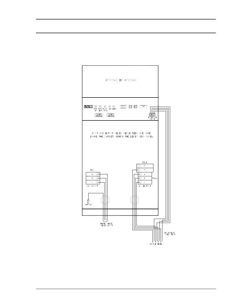
4.6.3 Output Wiring Diagram
Figure 4-7 shows the required output wiring connections for a BPS75 or BPS90 (rear panel view).
Always disconnect all input power from the BPS before removing the rear terminal block access panel.
Route the load wires through the strain relief clamps. Depending on wire size required, it may be
necessary to use two strain relief holes with 2 wires through each as shown.
Figure 4-7: BPS75-3 or BPS90-3 Output Wiring (Rear panel view)
See also other documents in the category AMETEK Equipment:
- CW-M (48 pages)
- CW-M Corrected Table 4-2 in (1 page)
- CW-P (62 pages)
- Lx Series (205 pages)
- CW Series Programming Manual (25 pages)
- Ls Series II Programming Manual (242 pages)
- Compact i/iX Series (157 pages)
- Compact IX 2253 (157 pages)
- Compact i/iX Series Software Manual (203 pages)
- ASD Series Quick Start (5 pages)
- ASD Series (120 pages)
- i-iX Series II Programming Manual (226 pages)
- DLM 600W Series Programming Manual (24 pages)
- M131 Programming Manual (99 pages)
- DLM Series (74 pages)
- DLM 600W Series (82 pages)
- DLM600 Series (16 pages)
- DLM-E 4kW Series Programming Manual (32 pages)
- DCS-E 1.2kW Series (65 pages)
- M136 (8 pages)
- DCS-E 3kW Series (94 pages)
- CTS 3.0 (166 pages)
- CSW Series (174 pages)
- 2003RP (126 pages)
- 2001RP (131 pages)
- MX CTSH (151 pages)
- MXCTSL Administrator Manual (27 pages)
- MX CTSL (157 pages)
- RS Series (228 pages)
- MX Series Installation Manual (35 pages)
- Ls AC source (2 pages)
- MX15 Series (184 pages)
- Ls Series II (226 pages)
- Lx Series Driver Manual (275 pages)
- MX Series Rev: AY (257 pages)
- iX Series (341 pages)
- i-iX Series II (258 pages)
- GUPS 2400A-108 (36 pages)
- HPD Series (58 pages)
- HPD Series Operation Manual (41 pages)
- HPD Series GPIB-Multichannel (134 pages)
- PLA-PLW Programming Manual (74 pages)
- ReFlex Mating Connnectors for Controller (3 pages)
- LPDC-16V (4 pages)