Multiplexer redundancy – Adtec digital DTA-3050 (version 6.02.14) Manual User Manual
Page 65
Multiplexer Redundancy
The DTA-3050 is designed to provide 1:1 encoder redundancy when connected to a second DTA-3050 encoder. No external
redundancy switch is required to provide 1:1 redundancy – all redundancy support is contained in the unit. The secondary
Multiplexer will be “upstream” to the primary Multiplexer. When the secondary is online, the output will flow through the
primary. When the secondary is offline, then the output will simply terminate into the primary and the primary’s output will be
the egress present at the output.
Redundancy is controlled by the primary Multiplexer. A relay has been added to the product and when the normally closed
(NC) circuit, in its non-energized state, will route the secondary traffic to the output. When the relay is energized, output will be
from the primary mux.
To determine the status of an encoder (Primary / Secondary), the user can look in the upper-right corner of the LCD display.
The LCD screen shows a letter to denote the redundancy status:
P = Primary
•
S = Secondary.
•
A blank in the upper-right hand corner denotes stand-alone mode.
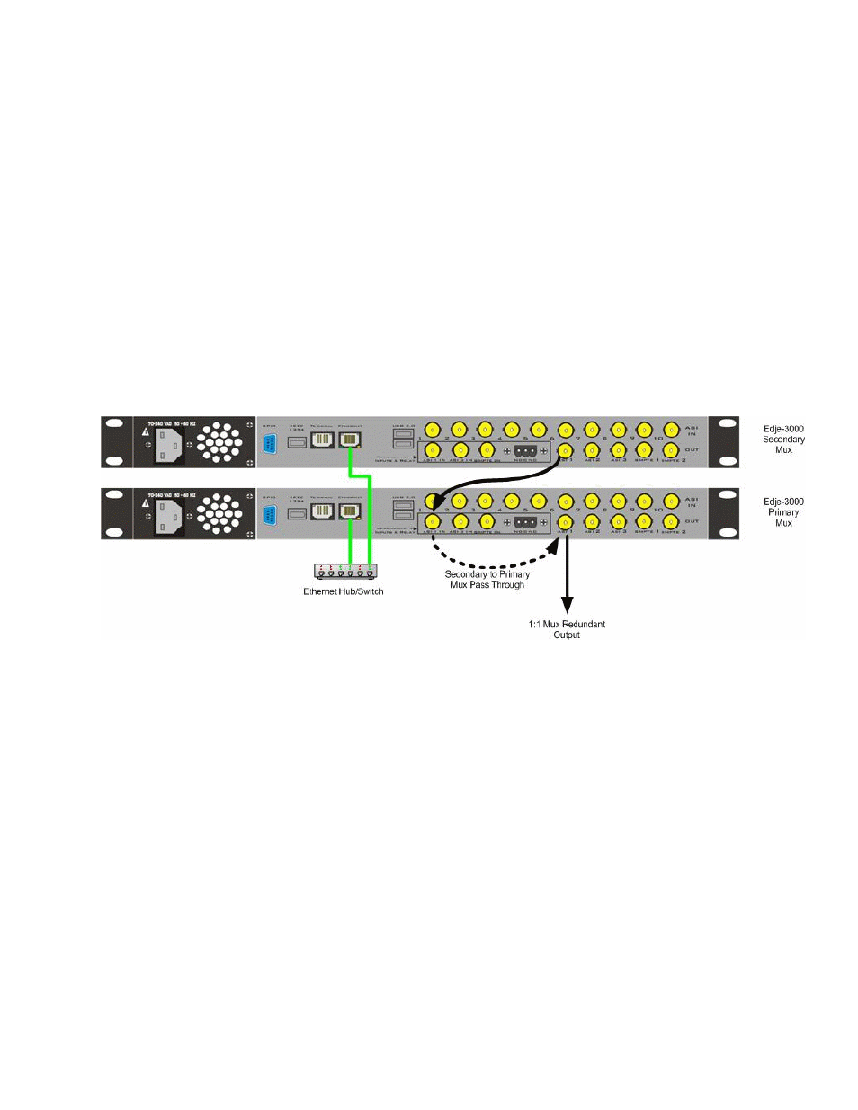
Connections
Redundancy is achieved by cabling two DTA-3050’s in a serial fashion as shown in the following figure:
57
User Interface