Back panel, Connectivity features, Back panel connectivity features – Adtec digital DTA-3050 (version 6.02.14) Manual User Manual
Page 15
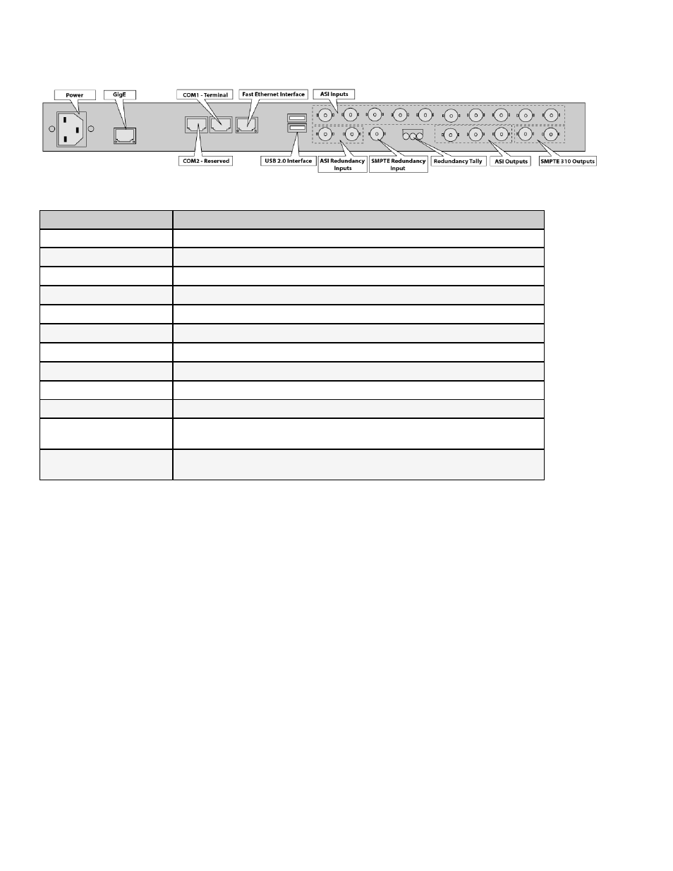
Back Panel
Illustration:
Connectivity Features
Connection
Purpose
Power
standard 12V A/C electrical power connection
GigE
used for IP Egress
Terminal Interface
used to communicate with a PC for serial communications
Fast Ethernet Interface
management of the DTA-Control GUI
Serial Port
used to communicate with redundancy switch
USB 2.0 Interface (2)
for future use (not currently supported in documentation)
ASI Inputs (10)
Asynchronous Serial Inputs (receive programming)
ASI Redundancy Inputs (2)
used to link 2 Muxers (DTA3050's) in tandem; one as primary, one as backup
SMPTE Redundancy Input
used to link 2 Muxers (DTA3050's) in tandem; one as primary, one as backup
Redundancy Tally
used to hookup an external alarm device
ASI Outputs (3)
triple-mirrored ASI Outputs
the first two connectors are used for redundant set-ups
SMPTE 310 Outputs (2)
mirrored SMPTE Output
the first connector is used for redundant set-ups
Getting Started
12