10/100 ethernet (fpga), 10/100 ethernet (fpga) –26 – Altera Arria V SoC Development Board User Manual
Page 34
2–26
Chapter 2: Board Components
Components and Interfaces
July 2014
Altera Corporation
Reference Manual
The Micrel KSZ9021RN PHY uses a multi-level POR bootstrap encoding scheme to
allow a small set of I/O pins (7) to set up a very large number of default settings
within the device. The related I/O pins have integrated pull-up or pull-down resistors
to configure the device.
lists the level encoding scheme.
10/100 Ethernet (FPGA)
The development board supports an RJ-45 10/100 base-T Ethernet using an external
Renesas uPD60620 PHY. This PHY supports EtherCAT, Ethernet IRT and DLR
features using a third party MAC IP. The PHY-to-MAC interface employs MII
connection using four data lines at 25 Mbps each for a connection speed of 100 Mbps.
The PHY uses 3.3-V power rails and requires a 25 MHz reference clock to be driven
from a dedicated oscillator. The PHY interfaces to a dual RJ-45 model with internal
magnetics that can be used for driving copper lines with Ethernet traffic.
21
ENET_HPS_TXD2
K18
3.3-V CMOS
RGMII transmit data bus
22
ENET_HPS_TXD3
M18
3.3-V CMOS
RGMII transmit data bus
3
MDI_HPS_N0
—
3.3-V CMOS
Media dependent interface
6
MDI_HPS_N1
—
3.3-V CMOS
Media dependent interface
8
MDI_HPS_N2
—
3.3-V CMOS
Media dependent interface
11
MDI_HPS_N3
—
3.3-V CMOS
Media dependent interface
2
MDI_HPS_P0
—
3.3-V CMOS
Media dependent interface
5
MDI_HPS_P1
—
3.3-V CMOS
Media dependent interface
7
MDI_HPS_P2
—
3.3-V CMOS
Media dependent interface
10
MDI_HPS_P3
—
3.3-V CMOS
Media dependent interface
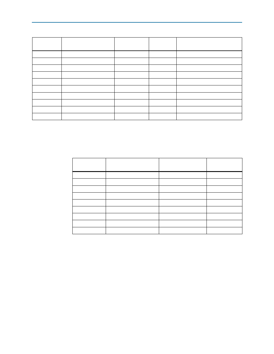
Table 2–17. Ethernet PHY (HPS) Pin Assignments, Signal Names and Functions (Part 2 of 2)
Board
Reference (U7)
Schematic Signal Name
Arria V SoC Pin
Number
I/O Standard
Description
Table 2–18. Ethernet PHY (HPS) Bootstrap Encoding Scheme
Board Reference
(U7)
Schematic Signal Name
Description
Strapping Option
17
ENET_HPS_LED1_LINK
PHY address bit 0
Pulled low
15
ENET_HPS_LED2_LINK
PHY address bit 1
Pulled low
32
ENET_HPS_RXD0
Mode 0
Pulled high
31
ENET_HPS_RXD1
Mode 1
Pulled high
28
ENET_HPS_RXD2
Mode 2
Pulled high
27
ENET_HPS_RXD3
Mode 3
Pulled high
35
ENET_HPS_RX_CLK
PHY address bit 2
Pulled high
33
ENET_HPS_RX_DV
Clock enable
Pulled low
41
CLK125_NDO_LED_MODE
Single LED mode
Pulled high