Rotary switch, Clock circuitry, Stratix iv e fpga clocks – Altera Stratix IV E FPGA Development Board User Manual
Page 30: Rotary switch –22, Clock circuitry –22, Stratix iv e fpga clocks –22
2–22
Chapter 2: Board Components
Clock Circuitry
Stratix IV E FPGA Development Board Reference Manual
May 2011
Altera Corporation
Rotary Switch
The 16-position rotary switch (SW5) is wired to the MAX
II CPLD EPM2210 System
Controller. This rotary switch serves the following purposes:
■
At power-up or when the reset configuration push-button switch (S1) is pressed,
this switch selects either the factory (page 0) or the user (page 1) design to load
into the FPGA. The FPGA reconfiguration can also be done by writing a logic 1 to
the srst register over the FSM bus in the MAX
II CPLD EPM2210 System
Controller.
■
After power-up, the rotary switch selects the power rail monitored from among a
total of 12 rails. The power information is displayed in the Power GUI on a host PC
with a USB connection to the board.
■
User applications can obtain the switch value by reading the rsr register over the
FSM bus in the MAX
II CPLD EPM2210 System Controller.
Refer to
for the specific power rails that are measured based
on the rotary switch position.
Table 2–21
lists the rotary switch component reference and manufacturing
information.
Clock Circuitry
This section describes the board's clocking circuitry.
Stratix IV E FPGA Clocks
The development board has several on-board oscillators.
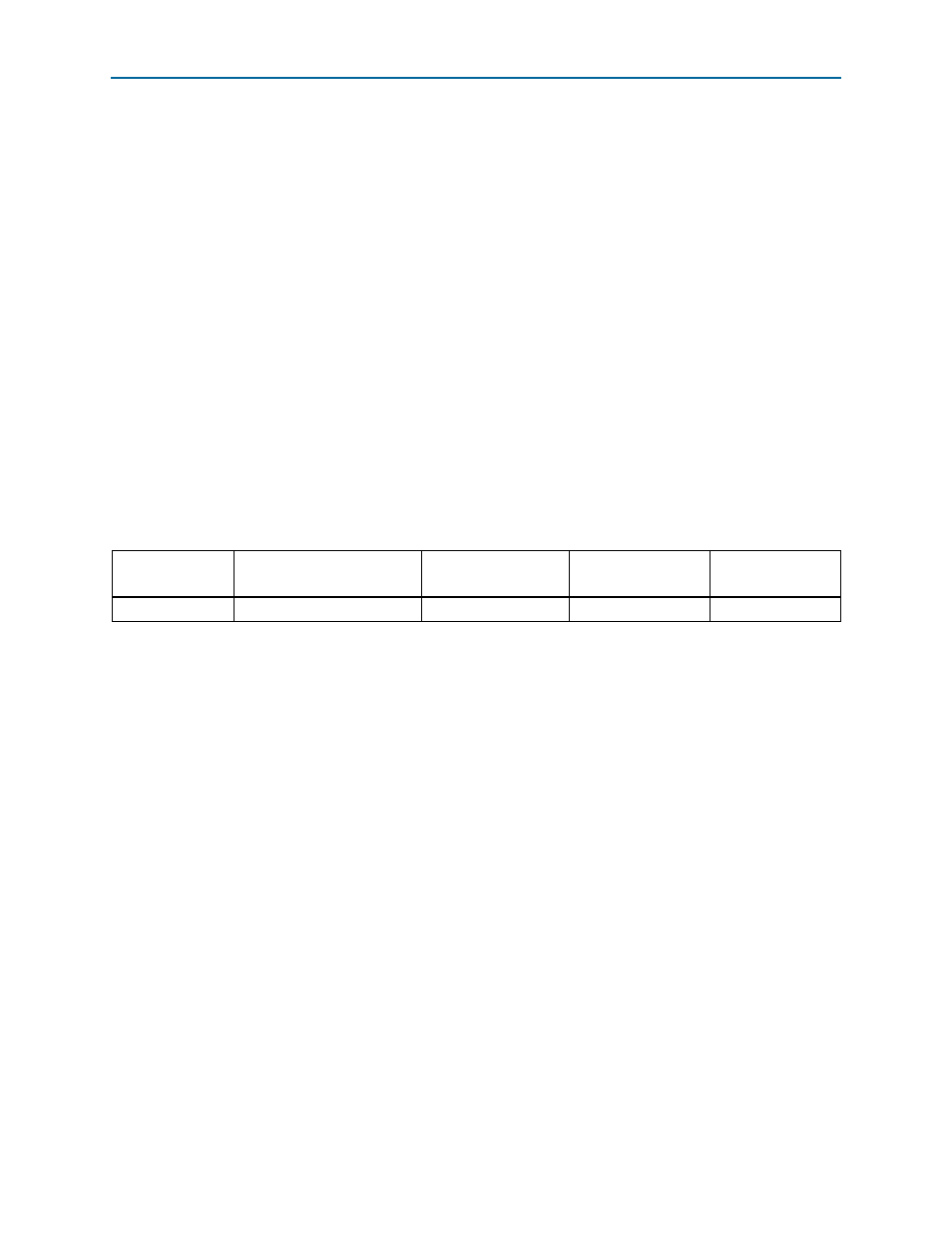
Table 2–21. Rotary Switch Component Reference and Manufacturing Information
Board Reference
Description
Manufacturer
Manufacturer
Part Number
Manufacturer
Website
SW5
16-position rotary switch
Grayhill
94HCB16WT