Altera Stratix IV E FPGA Development Board User Manual
Page 24
2–16
Chapter 2: Board Components
Configuration, Status, and Setup Elements
Stratix IV E FPGA Development Board Reference Manual
May 2011
Altera Corporation
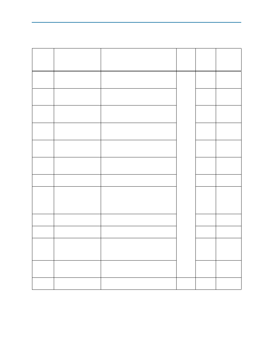
lists the LED board references, names, and functional descriptions.
Table 2–8. Board-Specific LEDs (Part 1 of 2)
Board
Reference
Schematic Signal Name
Description
I/O
Standard
Stratix IV
E Device
Pin
Number
Other
Connections
D11
ENET_LED_TX
Green LED. Illuminates to indicate Ethernet
PHY transmit activity. Driven by the Marvell
88E1111 PHY.
2.5-V
—
—
D12
ENET_LED_RX
Green LED. Illuminates to indicate Ethernet
PHY receive activity. Driven by the Marvell
88E1111 PHY.
—
—
D7
ENET_LED_LINK10
Green LED. Illuminates to indicate Ethernet
linked at 10 Mbps connection speed.
Driven by the Marvell 88E1111 PHY.
—
—
D8
ENET_LED_LINK100
Green LED. Illuminates to indicate Ethernet
linked at 100 Mbps connection speed.
Driven by the Marvell 88E1111 PHY.
—
—
D9
ENET_LED_LINK1000
Green LED. Illuminates to indicate Ethernet
linked at 1000 Mbps connection speed.
Driven by the Marvell 88E1111 PHY.
N32
—
D10
ENET_LED_DUPLEX
Green LED. Illuminates to indicate Ethernet
PHY is operating in Duplex mode. Driven
by the Marvell 88E1111 PHY.
—
—
D15
MAX_EMB
(labeled USER_1
on the board)
Green LED. Illuminates to indicate which
configuration page is loaded.
—
U10.E15
D17
MAX_LOAD
Green LED. Illuminates when the MAX II
CPLD EPM2210 System Controller is
actively configuring the FPGA. Driven by
the MAX II CPLD EPM2210 System
Controller.
—
U10.H14
D18
MAX_FACTORY
Green LED. Illuminates when FPGA is
configured with the default factory design.
—
U10.G16
D19
MAX_USER
(labeled
USER_2
on the board)
Green LED. Illuminates to indicate which
configuration page is loaded.
—
U10.G12
D20
MAX_ERROR
Red LED. Illuminates when the MAX II
CPLD EPM2210 System Controller fails to
configure the FPGA. Driven by the MAX II
CPLD EPM2210 System Controller.
—
U10.H15
D22
FPGA_CONF_DONE
Green LED. Illuminates when the FPGA is
successfully configured. Driven by the
MAX II CPLD EPM2210 System Controller.
AH29
U10.E3
D21
12V
Blue LED. Illuminates when 12-V power rail
is active.
—
—
—