Status elements, Status elements –15 – Altera Stratix IV E FPGA Development Board User Manual
Page 23
Chapter 2: Board Components
2–15
Configuration, Status, and Setup Elements
May 2011
Altera Corporation
Stratix IV E FPGA Development Board Reference Manual
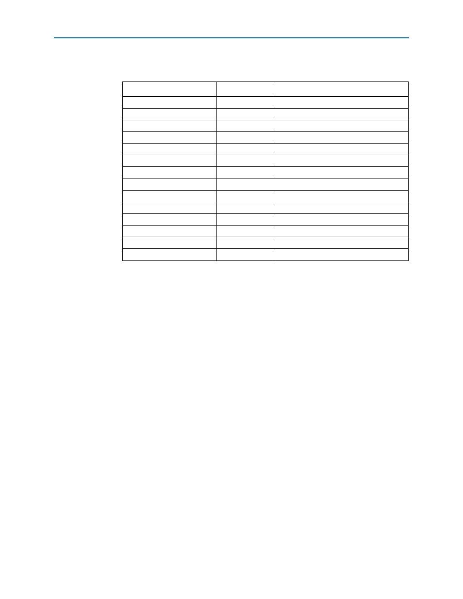
Table 2–7
shows the flash memory map storage.
There are two pages reserved for the FPGA configuration data. The factory hardware
page is considered page 0 and is loaded upon power-up if the rotary switch is set to
'0'. Otherwise, the user hardware page 1 is loaded.
f
For more information on the following topics, refer to the respective documents:
■
Board Update Portal, re
■
PFL design, refer to the
■
PFL megafunction, refer to
Status Elements
The development board includes general user, board specific, and status LEDs. This
section describes the status elements.
Table 2–7. Flash Memory Map
Block Description
Size
Address Range
Unused
32 KB
0x03FF8000 - 0x03FFFFFF
Unused
32 KB
0x03FF0000 - 0x03FF7FFF
Unused
32 KB
0x03FE8000 - 0x03FEFFFF
Unused
32 KB
0x03FE0000 - 0x03FE7FFF
User software
11,669 KB
0x034C0000 - 0x03FDFFFF
User hardware
21,627 KB
0x02020000 - 0x034BFFFF
Reserved
128 KB
0x02000000 - 0x0201FFFF
zipfs (html, web content)
5,898 KB
0x01A60000 - 0x01FFFFFF
Factory software
5,898 KB
0x014C0000 - 0x01A5FFFF
Factory hardware
21,627 KB
0x00020000 - 0x014BFFFF
PFL option bits
32 KB
0x00018000 - 0x0001FFFF
Reserved
32 KB
0x00010000 - 0x00017FFF
Ethernet option bits
32 KB
0x00008000 - 0x0000FFFF
User design reset vector
32 KB
0x00000000 - 0x00007FFF