Step 2: constraints, Step 3: set up simulation, Figure 2–2 – Altera QDRII SRAM Controller MegaCore Function User Manual
Page 17
Altera Corporation
MegaCore Version 9.1
2–7
November 2009
QDRII SRAM Controller MegaCore Function User Guide
Getting Started
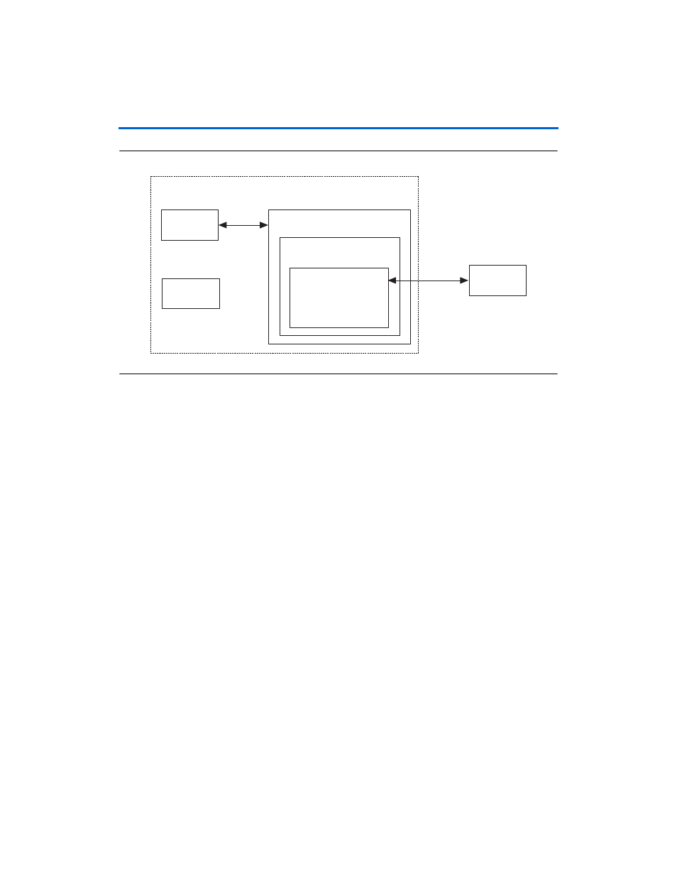
Figure 2–2. System Naming
14. IP Toolbench uses a prefix (e.g., qdrii_) for the names of all memory
interface pins. Enter a prefix for all memory interface pins
associated with this custom variation.
15. Click Finish.
Step 2: Constraints
To choose the constraints for your device, follow these steps:
1.
Click Step 2: Constraints in IP Toolbench.
2.
Choose the positions on the device for each of the QDRII SRAM
byte groups. To place a byte group, select the byte group in the
drop-down box at your chosen position.
1
The floorplan matches the orientation of the Quartus II
floorplanner. The layout represents the die as viewed from
above. A byte group consists of a cq pin and a number of q
pins (the same number as the data width).
Step 3: Set Up Simulation
An IP functional simulation model is a cycle-accurate VHDL or Verilog
HDL model produced by the Quartus II software. The model allows for
fast functional simulation of IP using industry-standard VHDL and
Verilog HDL simulators.
QDRII SRAM
Other Logic
PLL
QDRII SRAM
Interface
example_top
Example Design
QDRII SRAM Controller
my_system_inst
System
sub_system_inst
Subsystem